Page 2416 of 3502

SERVICE DATA AND SPECIFICATIONS (SDS)PFP:00030
Wheel BearingBDS0007T
Drive ShaftBDS0007U
Dynamic DamperBDS0007V
Axial end play0.05 mm (0.002 in) or less")
FAX-34
SERVICE DATA AND SPECIFICATIONS (SDS)
SERVICE DATA AND SPECIFICATIONS (SDS)PFP:00030
Wheel BearingBDS0007T
Drive ShaftBDS0007U
Dynamic DamperBDS0007V
Axial end play0.05 mm (0.002 in) or less
Joint Wheel side Transaxle side
Grease quantityQR20DE models
88 – 108 g (3.10 – 3.80 oz)132 – 142 g (4.66 – 5.00 oz)
VQ23DE models 124 – 134 g (4.37 – 4.73 oz)
VQ35DE models 115 – 125 g (4.06 – 4.41 oz) 134 – 144 g (4.73 – 5.08 oz)
Boots installed
lengthQR20DE models
141.7 – 143.7 mm (5.58 – 5.66 in)180.7 – 182.7 mm (7.11 – 7.19 in) (Left side)
176.8 – 178.8 mm (6.96 – 7.04 in) (Right side)
VQ23DE models194.5 – 196.5 mm (7.66 – 7.74 in) (Left side)
190.6 – 192.6 mm (7.50 – 7.58 in) (Right side)
VQ35DE models 155.3 – 161.3 mm (6.11 – 6.35 in)190.7 mm (7.51 in) (Left side)
186.8 mm (7.35 in) (Right side)
Dimension AQR20DE modelsLeft side
205 – 215 mm (8.07 – 8.46 in)
Right side
VQ23DE modelsLeft side 205 – 215 mm (8.07 – 8.46 in)
Right side 199 – 202 mm (7.83 – 7.95 in)
VQ35DE modelsLeft side 205 – 215 mm (8.07 – 8.46 in)
Right side —
Dimension BQR20DE modelsLeft side
50 mm (1.97 in)
Right side
VQ23DE modelsLeft side
70 mm (2.76 in)
Right side
VQ35DE modelsLeft side 70 mm (2.76 in)
Right side —
FAC0156D
Page 2433 of 3502
 of each com")
FRONT SUSPENSION ASSEMBLY
FSU-5
C
D
F
G
H
I
J
K
L
MA
B
FSU
FRONT SUSPENSION ASSEMBLYPFP:54010
On-Vehicle Inspection BES0003K
Make sure that the mounting conditions (looseness, back lash) of each component and component status
(wear, damage) are normal.
INSPECTION OF TRANSVERSE LINK BALL JOINT END PLAY
1. Set front wheels in a straight-ahead position. Do not depress brake pedal.
2. Measure axial end play by placing an iron pry bar or a similar item between suspension arm and strut
assembly and prying up and down.
CAUTION:
Be careful not to damage ball joint boot. Do not damage the installation position by applying
excessive force.
STRUT INSPECTION
Check for oil leakage, damage, and breakage of installation positions.
Wheel Alignment InspectionBES0003L
DESCRIPTION
Measure wheel alignment under unladen conditions.
NOTE:
“Unladen” conditions mean that fuel, engine coolant, and lubricant are full. A spare tire, a jack, hand tools and
mats are in designated positions.
PRELIMINARY CHECK
1. Check Tires for improper air pressure and wear.
2. Check Road wheels for runout. Refer to WT-3, "
ROAD WHEEL" .
3. Check Wheel bearing axial end play. Refer to FAX-5, "
WHEEL BEARING INSPECTION" .
4. Check Transverse link ball joint axial end play. Refer to FSU-14, "
INSPECTION AFTER REMOVAL" .
5. Check Strut operation.
6. Check Each mounting point of axle and suspension for looseness and deformation.
7. Check Each link, rod, and member for cracks, deformation and other damage.
8. Check Vehicle height (posture).
INSPECTION OF CAMBER, CASTER AND KINGPIN INCLINATION ANGLES.
�Camber, caster, kingpin inclination angles cannot be adjusted.
�Before inspection, mount wheels onto turning radius gauge. Mount rear wheels onto a stand that has
same height so vehicle will remain horizontal.
Using a CCK Gauge
Install CCK gauge attachment [SST:KV991040S0] with the following procedure on wheel, then measure wheel
alignment.
1. Remove three wheel nuts, and install the guide bolts to hub
bolts.
2. Screw adapter into the plate until it contacts the plate tightly.
3. Screw center plate into the plate.
4. Insert plate on guide bolt. Put spring in, and then evenly screw
both guide bolt nuts. When fastening guide bolt nuts, do not
completely compress the spring.Axial end play : 0 mm (0 in)
SEIA0240E
Page 2442 of 3502

FSU-14
TRANSVERSE LINK
TRANSVERSE LINKPFP:54500
Removal and InstallationBES0003Q
REMOVAL
1. Remove tires from vehicle.
2. Remove fixing nut and bolt of transverse link ball joint, and then separate transverse link from steering
knuckle.
3. Remove transverse link mounting bolts, and then remove transverse link from front suspension member.
INSPECTION AFTER REMOVAL
Visual Inspection
�Check transverse link and bushing for deformation, cracks, and other damage. Replace transverse link if
there are.
�Check ball joint boot for cracks, damage, and leakage of grease. Replace transverse link if there are.
Ball Joint Inspection
Manually move ball stud to confirm it moves smoothly with no binding.
Swing Torque Inspection
CAUTION:
Move the ball joint at least ten times by hand to check for smooth movement before measuring.
�Hook a spring balance at the cotter pin mounting hole. Make
sure that the spring balance measurement value is within the
specified value when ball stud begins moving.
�Replace transverse link if value is outside the standard.
Rotating Torque Inspection
�Install nut to the ball stud, and make sure that the rotating torque
is within the standard using a preload gauge [SST].Swing torque:
0.5 – 3.4 N·m (0.06 – 0.34 kg-m, 5 – 30 in–lb)
Spring balance measurement:
13.5 – 91.9 N (1.4 – 9.3kg, 3.08 – 20.5 lb)
SEIA0523E
Rotating torque:
0.5 – 3.4 Nm (0.06 – 0.34 kg-m 5 – 30 in–lb)
FAC1021D
Page 2456 of 3502
 and contain tightening torques,
lubrication points, section number of the PARTS CATALO")
GI-10
HOW TO USE THIS MANUAL
ComponentsBAS0007E
�THE LARGE ILLUSTRATIONS are exploded views (see the following) and contain tightening torques,
lubrication points, section number of the PARTS CATALOG (e.g. SEC. 440) and other information neces-
sary to perform repairs.
The illustrations should be used in reference to service matters only. When ordering parts, refer to the
appropriate PARTS CATALOG .
Components shown in an illustration may be identified by a circled number. When this style of illustration
is used, the text description of the components will follow the illustration.
SYMBOLS
1. Union bolt 2. Copper washer 3. Brake hose
4. Cap 5. Bleed valve 6. Sliding pin bolt
7. Piston seal 8. Piston 9. Piston boot
10. Cylinder body 11. Sliding pin 12. Torque member mounting bolt
13. Washer 14. Sliding pin boot 15. Bushing
16. Torque member 17. Inner shim cover 18. Inner shim
19. Inner pad 20. Pad retainer 21. Pad wear sensor
22. Outer pad 23. Outer shim 24. Outer shim cover
1: PBC (Poly Butyl Cuprysil) grease
or silicone-based grease2: Rubber grease : Brake fluid
Refer to GI section for additional symbol definitions.
SFIA2959E
SAIA0749E
Page 3019 of 3502
CHASSIS AND BODY MAINTENANCE
MA-41
C
D
E
F
G
H
I
J
K
MA
B
MA
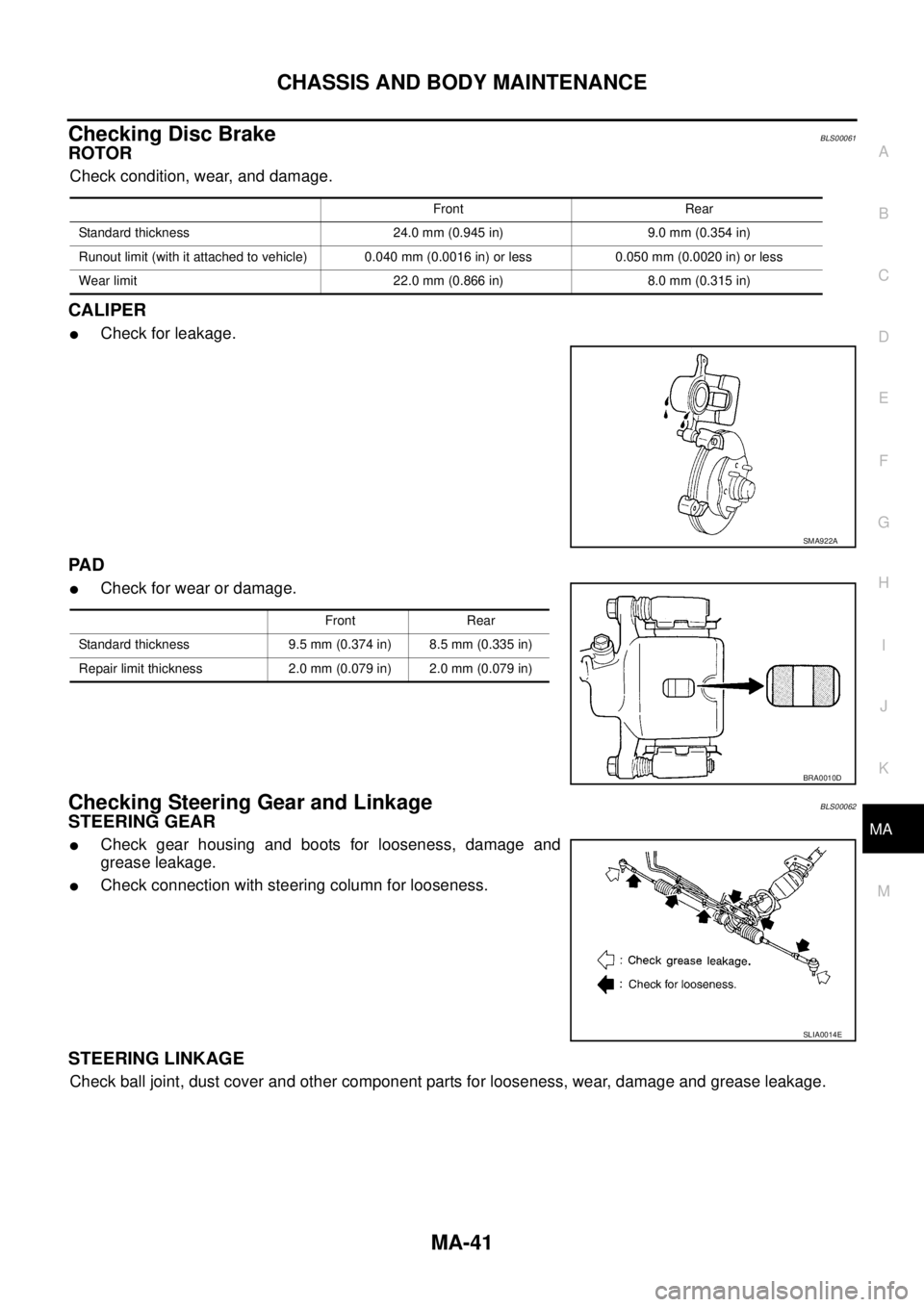
Checking Disc BrakeBLS00061
ROTOR
Check condition, wear, and damage.
CALIPER
�Check for leakage.
PA D
�Check for wear or damage.
Checking Steering Gear and LinkageBLS00062
STEERING GEAR
�Check gear housing and boots for looseness, damage and
grease leakage.
�Check connection with steering column for looseness.
STEERING LINKAGE
Check ball joint, dust cover and other component parts for looseness, wear, damage and grease leakage.
Front Rear
Standard thickness 24.0 mm (0.945 in) 9.0 mm (0.354 in)
Runout limit (with it attached to vehicle) 0.040 mm (0.0016 in) or less 0.050 mm (0.0020 in) or less
Wear limit 22.0 mm (0.866 in) 8.0 mm (0.315 in)
SMA922A
Front Rear
Standard thickness 9.5 mm (0.374 in) 8.5 mm (0.335 in)
Repair limit thickness 2.0 mm (0.079 in) 2.0 mm (0.079 in)
BRA0010D
SLIA0014E
Page 3020 of 3502

MA-42
CHASSIS AND BODY MAINTENANCE
Checking Power Steering Fluid and LinesBLS00063
Check fluid level in reservoir tank with engine off.
Use “HOT” range at fluid temperatures of 50 to 80°C (122 to 176°F)
or “COLD” range at fluid temperatures of 0 to 30°C (32 to 86°F).
CAUTION:
�Do not overfill.
�Recommended fluid is DEXRONTM III type ATF or equiva-
lent.
Refer to MA-14, "
RECOMMENDED FLUIDS AND LUBRI-
CANTS" .
�Check lines for improper attachment, leaks, cracks, dam-
age, loose connections, chafing and deterioration.
�Check rack boots for accumulation of power steering fluid.
Axle and Suspension PartsBLS00064
Check front and rear axle and suspension parts for excessive play,
cracks, wear or other damage.
�Shake each wheel to check for excessive play.
�Check wheel bearings for smooth operation.
�Check axle and suspension nuts and bolts for looseness.
�Check strut (shock absorber) for oil leakage or other damage.
�Check suspension ball joint for grease leakage and ball joint
dust cover for cracks or other damage.
SST850C
SST851C
SMA525A
SFA392B
Page 3021 of 3502
CHASSIS AND BODY MAINTENANCE
MA-43
C
D
E
F
G
H
I
J
K
MA
B
MA
Drive ShaftBLS00065
Check boot and drive shaft for cracks, wear, damage and grease
leakage.
Lubricating Locks, Hinges and Hood LatchBLS00066
SFA108A
PIIB0598E
Page 3121 of 3502

POWER STEERING FLUID
PS-7
C
D
E
F
H
I
J
K
L
MA
B
PS
POWER STEERING FLUIDPFP:KLF20
Checking Fluid LevelBGS0003P
�Check fluid level with the engine stopped.
�Make sure that fluid level is between MIN and MAX.
�Fluid levels at HOT and COLD are different. Do not confuse
them.
CAUTION:
�The fluid level should not exceed the MAX line. Excessive
fluid will cause fluid leakage from the cap.
�Do not reuse drained power steering fluid.
Checking Fluid LeakageBGS0003Q
Check hydraulic connections for fluid leakage, cracks, damage,
looseness, or wear.
1. Run engine until the fluid temperature reaches 50 to 80°C
(122 to 176°F) in reservoir tank, and keep engine speed idle.
2. Turn steering wheel several times from full left stop to full right
stop.
3. Hold steering wheel at each lock position for five seconds and
carefully, check for fluid leakage.
CAUTION:
Do not hold the steering wheel in a locked position for more
than 10 seconds. (There is the possibility that oil pump may
be damaged.)
4. If fluid leakage at connections is noticed, then loosen flare nut and then retighten. Do not overtighten con-
nector as this can damage O-ring, washer and connector.
5. If fluid leakage from oil pump is noticed, check oil pump. Refer to PS-29, "
POWER STEERING OIL
PUMP" .
6. Check steering gear boots for accumulation of fluid, indicating from steering gear.
Air Bleeding Hydraulic SystemBGS0003R
If air bleeding is not complete, the following symptoms can be observed.
�Bubbles are created in reservoir tank.
�Clicking noise can be heard from oil pump.
�Excessive buzzing in oil pump.
NOTE:
Fluid noise may occur in the steering gear or oil pump. This does not affect performance or durability of
the system.
1. Turn steering wheel several times from full left stop to full right stop with engine off.
CAUTION:
Filling reservoir tank with fluid so as not to lower fluid level below the MIN line while steering
wheel turning.
2. Start engine and hold steering wheel at each lock position for 3 seconds at idle to check for fluid leakage.
3. Repeat step 2 above several times at approximately 3 second intervals.
CAUTION:
Do not hold the steering wheel in a locked position for more than 10 seconds. (There is the possi-
bility that oil pump may be damaged.)
4. Check fluid for bubbles and white contamination.
5. Stop engine if bubbles and white contamination do not drain out. Perform steps 2 to 3 above after waiting
until bubbles and white contamination drain out.HOT : Fluid temperature 50 – 80°C (122 – 176°F)
COLD : Fluid temperature 0 – 30°C (32 – 86°F)
SGIA0232J
SGIA0506E