Page 2736 of 3502
LT-48
HEADLAMP - HALOGEN TYPE -
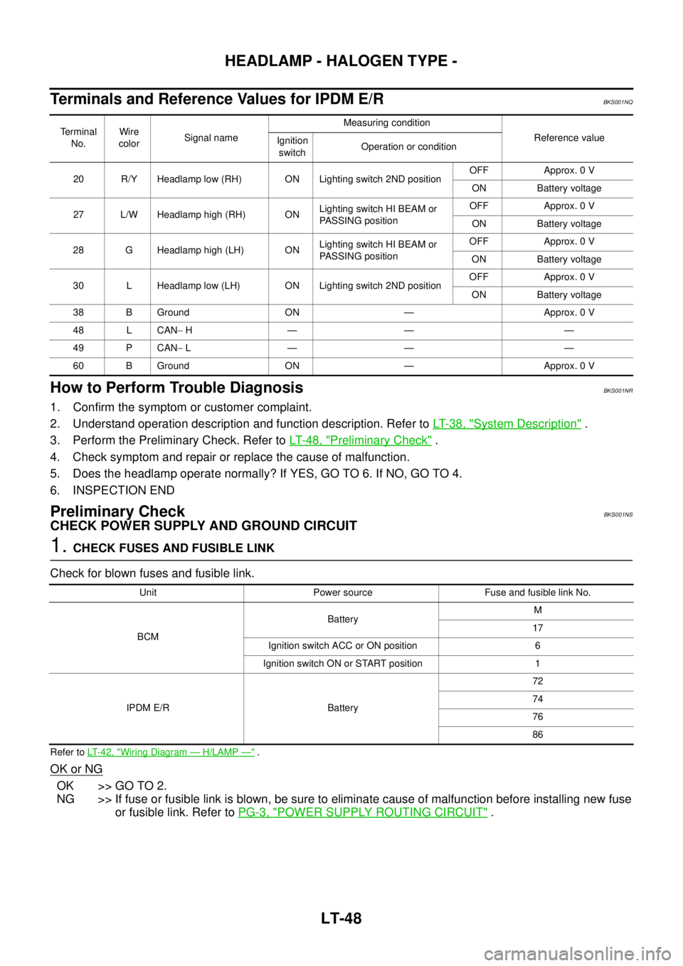
Terminals and Reference Values for IPDM E/RBKS001NQ
How to Perform Trouble DiagnosisBKS001NR
1. Confirm the symptom or customer complaint.
2. Understand operation description and function description. Refer to LT- 3 8 , "
System Description" .
3. Perform the Preliminary Check. Refer to LT- 4 8 , "
Preliminary Check" .
4. Check symptom and repair or replace the cause of malfunction.
5. Does the headlamp operate normally? If YES, GO TO 6. If NO, GO TO 4.
6. INSPECTION END
Preliminary CheckBKS001NS
CHECK POWER SUPPLY AND GROUND CIRCUIT
1. CHECK FUSES AND FUSIBLE LINK
Check for blown fuses and fusible link.
Refer to LT-42, "Wiring Diagram — H/LAMP —" .
OK or NG
OK >> GO TO 2.
NG >> If fuse or fusible link is blown, be sure to eliminate cause of malfunction before installing new fuse
or fusible link. Refer to PG-3, "
POWER SUPPLY ROUTING CIRCUIT" .
Terminal
No.Wire
colorSignal nameMeasuring condition
Reference value
Ignition
switchOperation or condition
20 R/Y Headlamp low (RH) ON Lighting switch 2ND positionOFF Approx. 0 V
ON Battery voltage
27 L/W Headlamp high (RH) ONLighting switch HI BEAM or
PASSING positionOFF Approx. 0 V
ON Battery voltage
28 G Headlamp high (LH) ONLighting switch HI BEAM or
PASSING positionOFF Approx. 0 V
ON Battery voltage
30 L Headlamp low (LH) ON Lighting switch 2ND positionOFF Approx. 0 V
ON Battery voltage
38 B Ground ON — Approx. 0 V
48 L CAN− H— — —
49 P CAN− L— — —
60 B Ground ON — Approx. 0 V
Unit Power source Fuse and fusible link No.
BCMBatteryM
17
Ignition switch ACC or ON position 6
Ignition switch ON or START position 1
IPDM E/R Battery72
74
76
86
Page 2754 of 3502
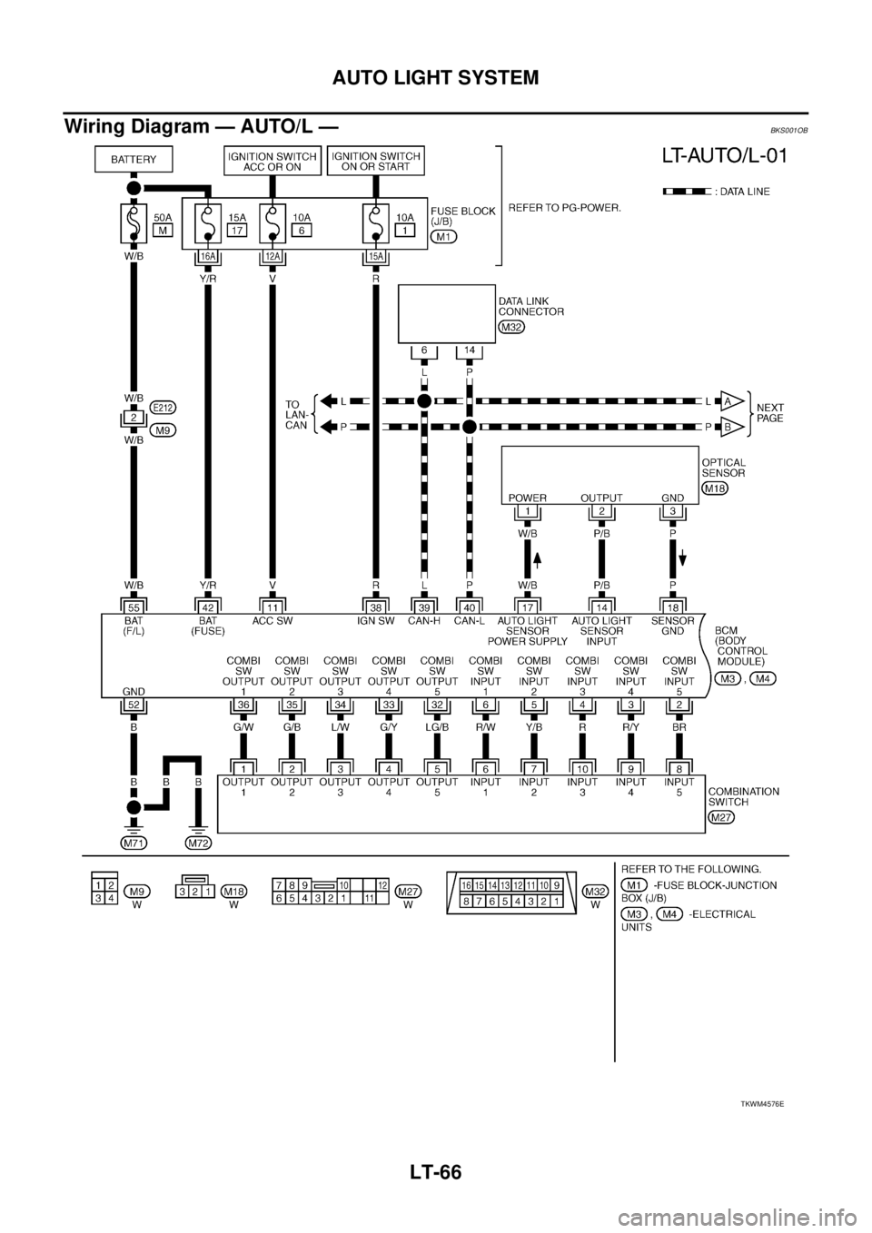
LT-66
AUTO LIGHT SYSTEM
Wiring Diagram — AUTO/L —BKS001OB
TKWM4576E
Page 2758 of 3502
LT-70
AUTO LIGHT SYSTEM
Preliminary CheckBKS001OF
SETTING CHANGE FUNCTIONS
Sensitivity of auto light system can be adjusted using CONSULT-II. Refer to LT- 1 9 , "WORK SUPPORT" .
CHECK POWER SUPPLY AND GROUND CIRCUIT
1. CHECK FUSES AND FUSIBLE LINK
Check for blown fuses and fusible link.
Refer to LT-66, "Wiring Diagram — AUTO/L —" .
OK or NG
OK >> GO TO 2.
NG >> If fuse or fusible link is blown, be sure to eliminate cause of malfunction before installing new fuse
or fusible link. Refer to PG-3, "
POWER SUPPLY ROUTING CIRCUIT" .
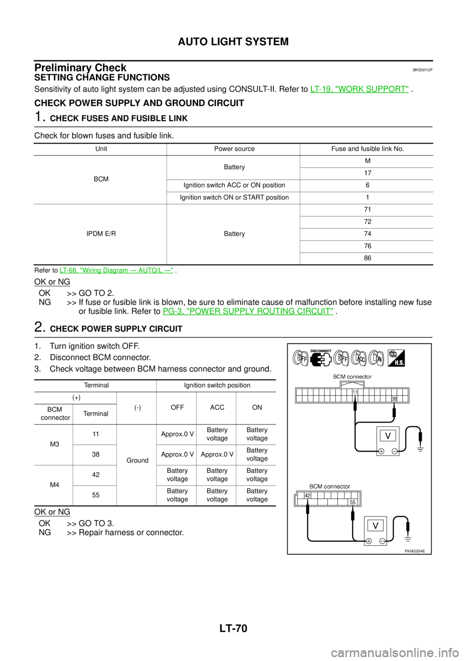
2. CHECK POWER SUPPLY CIRCUIT
1. Turn ignition switch OFF.
2. Disconnect BCM connector.
3. Check voltage between BCM harness connector and ground.
OK or NG
OK >> GO TO 3.
NG >> Repair harness or connector.
Unit Power source Fuse and fusible link No.
BCMBatteryM
17
Ignition switch ACC or ON position 6
Ignition switch ON or START position 1
IPDM E/R Battery71
72
74
76
86
Terminal Ignition switch position
(+)
(-) OFF ACC ON
BCM
connectorTerminal
M311
GroundApprox.0 VBattery
voltageBattery
voltage
38 Approx.0 V Approx.0 VBattery
voltage
M442Battery
voltageBattery
voltageBattery
voltage
55Battery
voltageBattery
voltageBattery
voltage
PKIA5204E
Page 2767 of 3502
ACTIVE AFS
LT-79
C
D
E
F
G
H
I
J
L
MA
B
LT
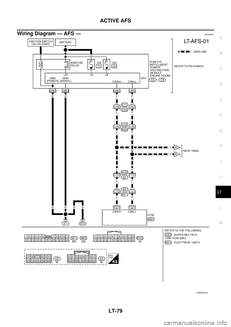
Wiring Diagram — AFS —BKS002F7
TKWM4587E
Page 2787 of 3502
HEADLAMP AIMING CONTROL (AUTO)
LT-99
C
D
E
F
G
H
I
J
L
MA
B
LT
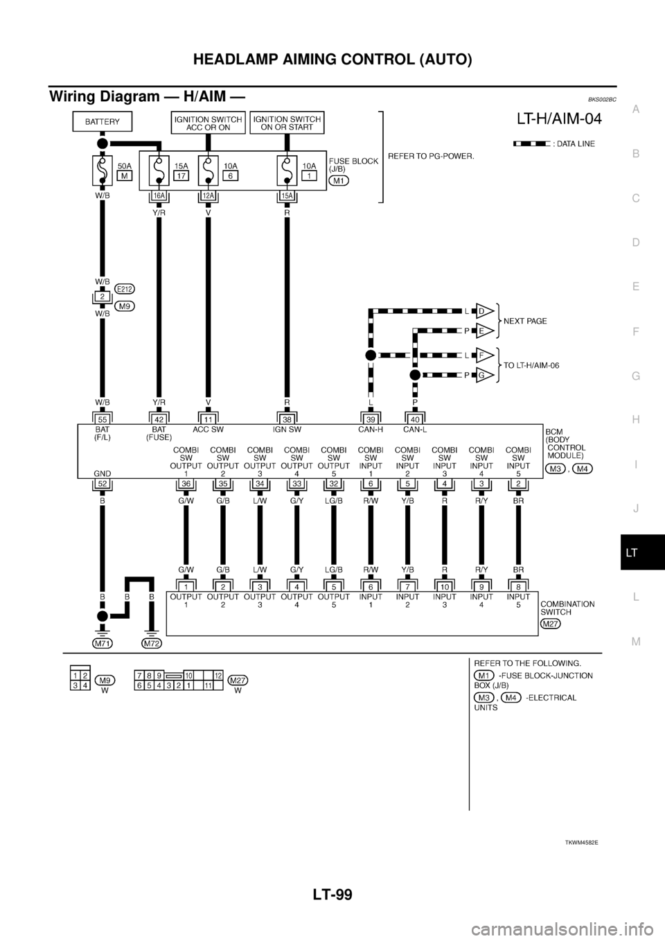
Wiring Diagram — H/AIM —BKS002BC
TKWM4582E
Page 2810 of 3502
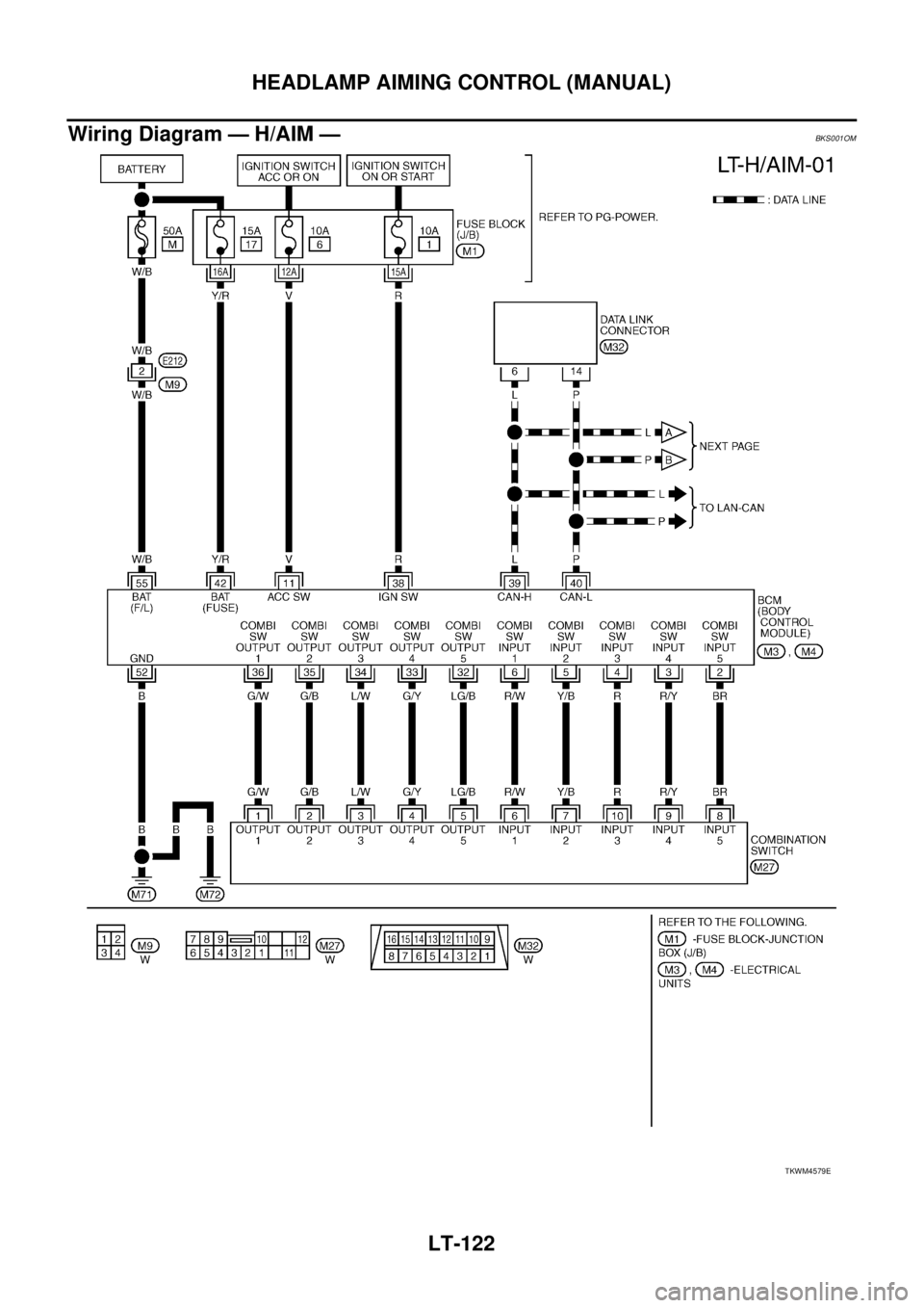
LT-122
HEADLAMP AIMING CONTROL (MANUAL)
Wiring Diagram — H/AIM —BKS001OM
TKWM4579E
Page 2817 of 3502
FRONT FOG LAMP
LT-129
C
D
E
F
G
H
I
J
L
MA
B
LT
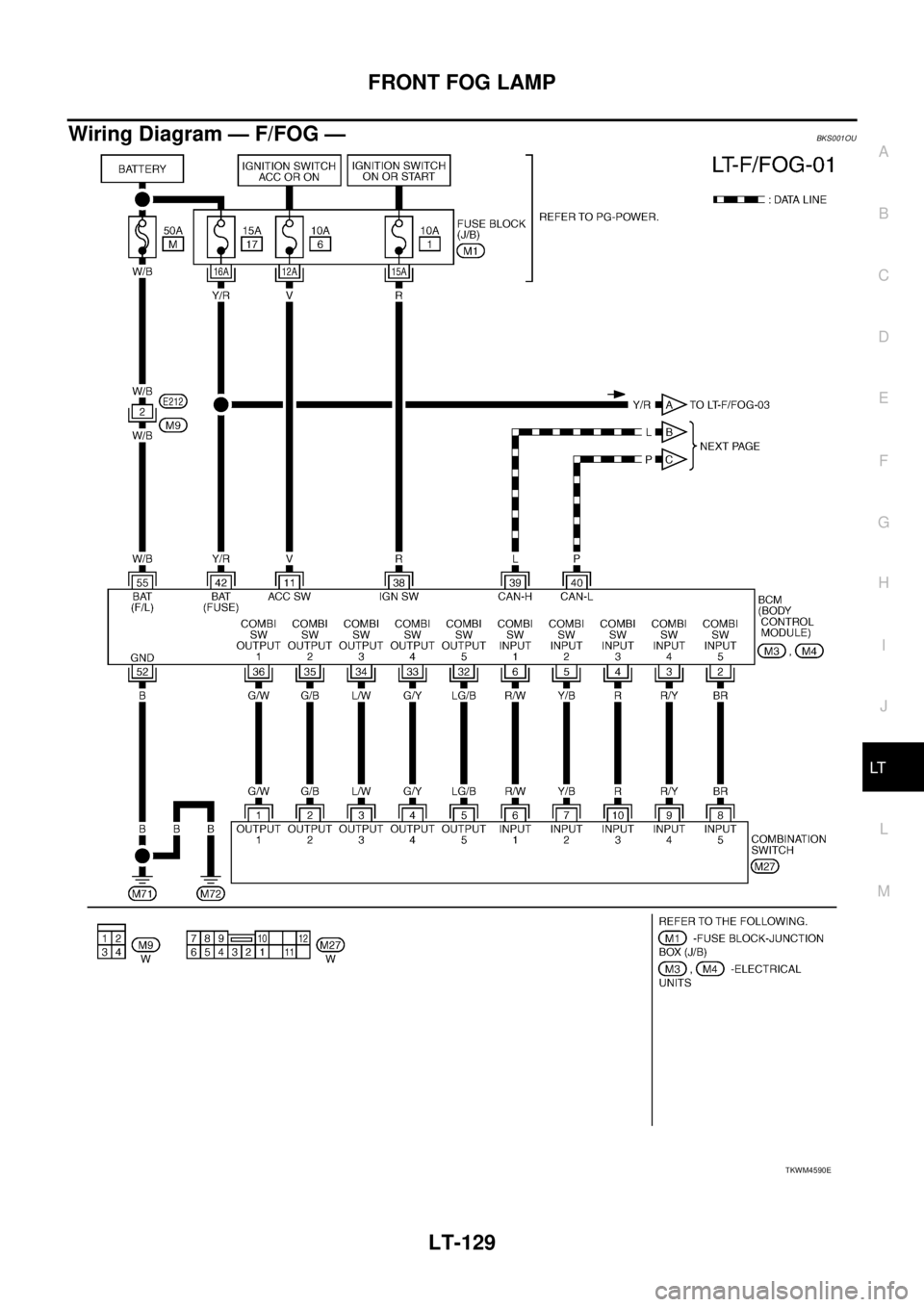
Wiring Diagram — F/FOG —BKS001OU
TKWM4590E
Page 2821 of 3502
FRONT FOG LAMP
LT-133
C
D
E
F
G
H
I
J
L
MA
B
LT
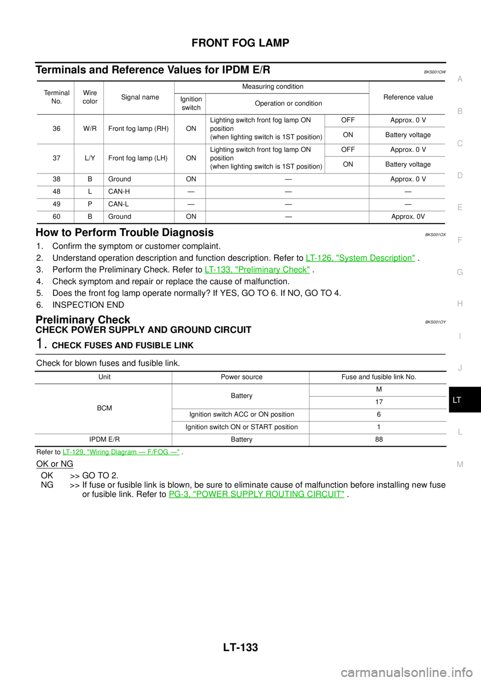
Terminals and Reference Values for IPDM E/RBKS001OW
How to Perform Trouble DiagnosisBKS001OX
1. Confirm the symptom or customer complaint.
2. Understand operation description and function description. Refer to LT- 1 2 6 , "
System Description" .
3. Perform the Preliminary Check. Refer to LT- 1 3 3 , "
Preliminary Check" .
4. Check symptom and repair or replace the cause of malfunction.
5. Does the front fog lamp operate normally? If YES, GO TO 6. If NO, GO TO 4.
6. INSPECTION END
Preliminary CheckBKS001OY
CHECK POWER SUPPLY AND GROUND CIRCUIT
1. CHECK FUSES AND FUSIBLE LINK
Check for blown fuses and fusible link.
Refer to LT-129, "Wiring Diagram — F/FOG —" .
OK or NG
OK >> GO TO 2.
NG >> If fuse or fusible link is blown, be sure to eliminate cause of malfunction before installing new fuse
or fusible link. Refer to PG-3, "
POWER SUPPLY ROUTING CIRCUIT" .
Terminal
No.Wire
colorSignal nameMeasuring condition
Reference value
Ignition
switchOperation or condition
36 W/R Front fog lamp (RH) ONLighting switch front fog lamp ON
position
(when lighting switch is 1ST position)OFF Approx. 0 V
ON Battery voltage
37 L/Y Front fog lamp (LH) ONLighting switch front fog lamp ON
position
(when lighting switch is 1ST position)OFF Approx. 0 V
ON Battery voltage
38 B Ground ON — Approx. 0 V
48 L CAN-H — — —
49 P CAN-L — — —
60 B Ground ON — Approx. 0V
Unit Power source Fuse and fusible link No.
BCMBatteryM
17
Ignition switch ACC or ON position 6
Ignition switch ON or START position 1
IPDM E/R Battery 88