Page 2832 of 3502
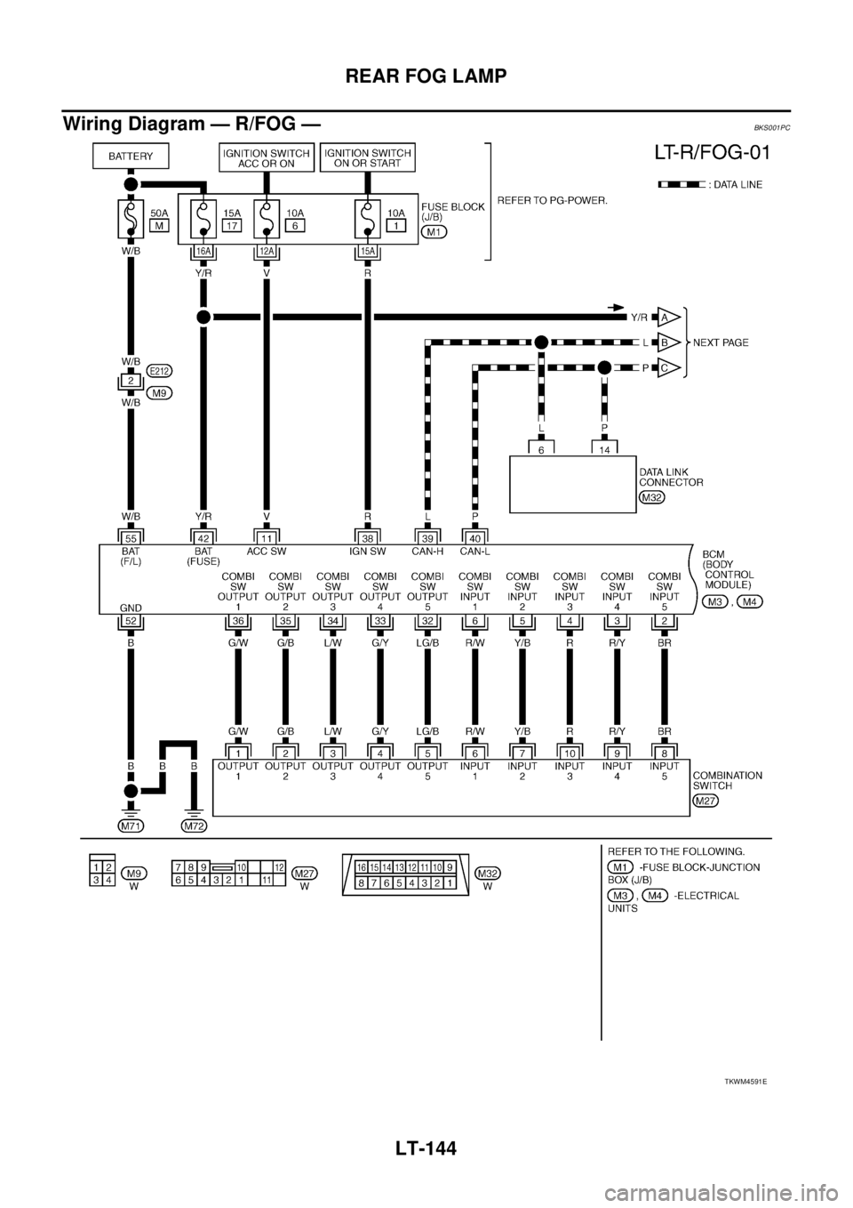
LT-144
REAR FOG LAMP
Wiring Diagram — R/FOG — BKS001PC
TKWM4591E
Page 2835 of 3502
REAR FOG LAMP
LT-147
C
D
E
F
G
H
I
J
L
MA
B
LT
How to Proceed With Trouble DiagnosisBKS001PE
1. Confirm the symptom or customer complaint.
2. Understand operation description and function description. Refer to LT- 1 4 2 , "
System Description" .
3. Perform the Preliminary Check. Refer toLT- 1 4 7 , "
Preliminary Check" .
4. Check symptom and repair or replace the cause of malfunction.
5. Does the rear fog lamp operate normally? If YES, GO TO 6. If NO, GO TO 4.
6. INSPECTION END
Preliminary CheckBKS001PF
CHECK POWER SUPPLY AND GROUND CIRCUIT
1. CHECK FUSES AND FUSIBLE LINK
Check for blown fuses and fusible link.
Refer to LT-144, "Wiring Diagram — R/FOG —" .
OK or NG
OK >> GO TO 2.
NG >> If fuse or fusible link is blown, be sure to eliminate cause of malfunction before installing new fuse
or fusible link. Refer to PG-3, "
POWER SUPPLY ROUTING CIRCUIT" .
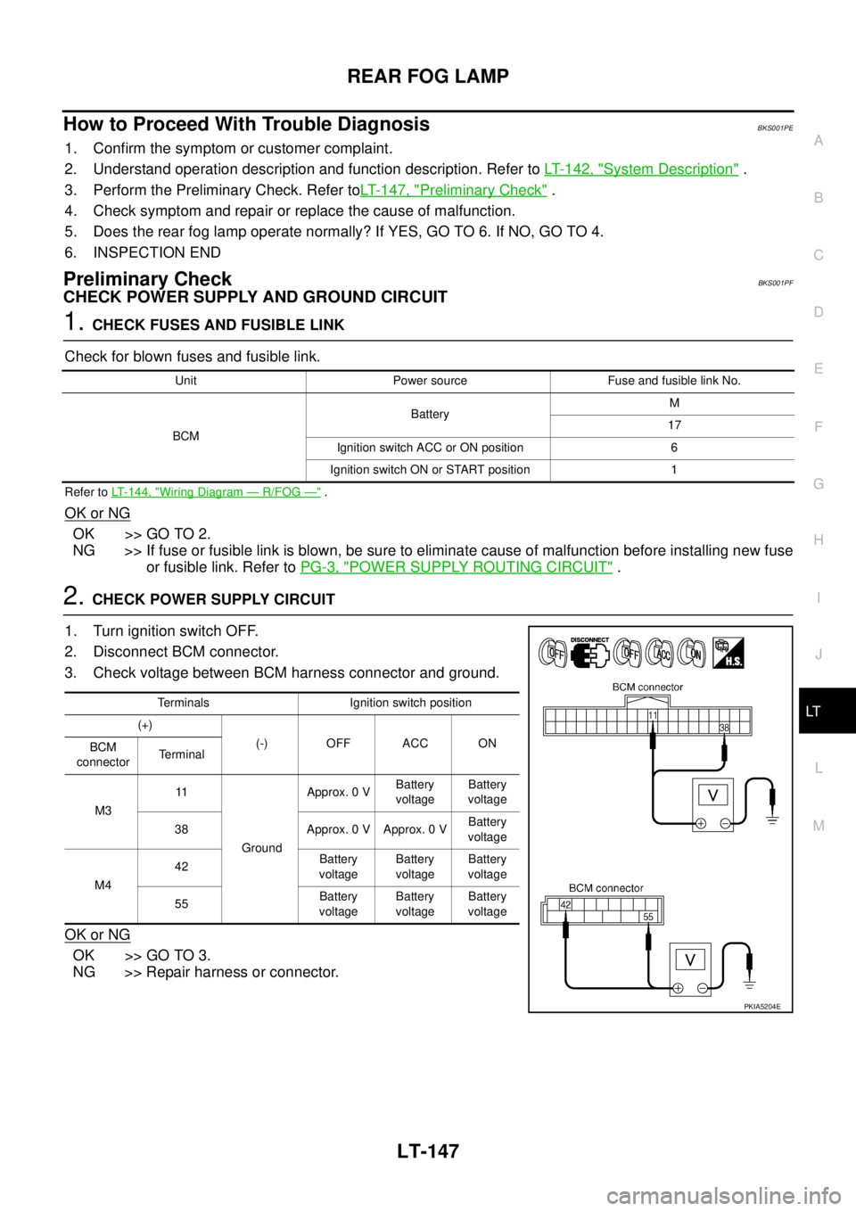
2. CHECK POWER SUPPLY CIRCUIT
1. Turn ignition switch OFF.
2. Disconnect BCM connector.
3. Check voltage between BCM harness connector and ground.
OK or NG
OK >> GO TO 3.
NG >> Repair harness or connector.
Unit Power source Fuse and fusible link No.
BCMBatteryM
17
Ignition switch ACC or ON position 6
Ignition switch ON or START position 1
Terminals Ignition switch position
(+)
(-) OFF ACC ON
BCM
connectorTerminal
M311
GroundApprox. 0 VBattery
voltageBattery
voltage
38 Approx. 0 V Approx. 0 VBattery
voltage
M442Battery
voltageBattery
voltageBattery
voltage
55Battery
voltageBattery
voltageBattery
voltage
PKIA5204E
Page 2844 of 3502
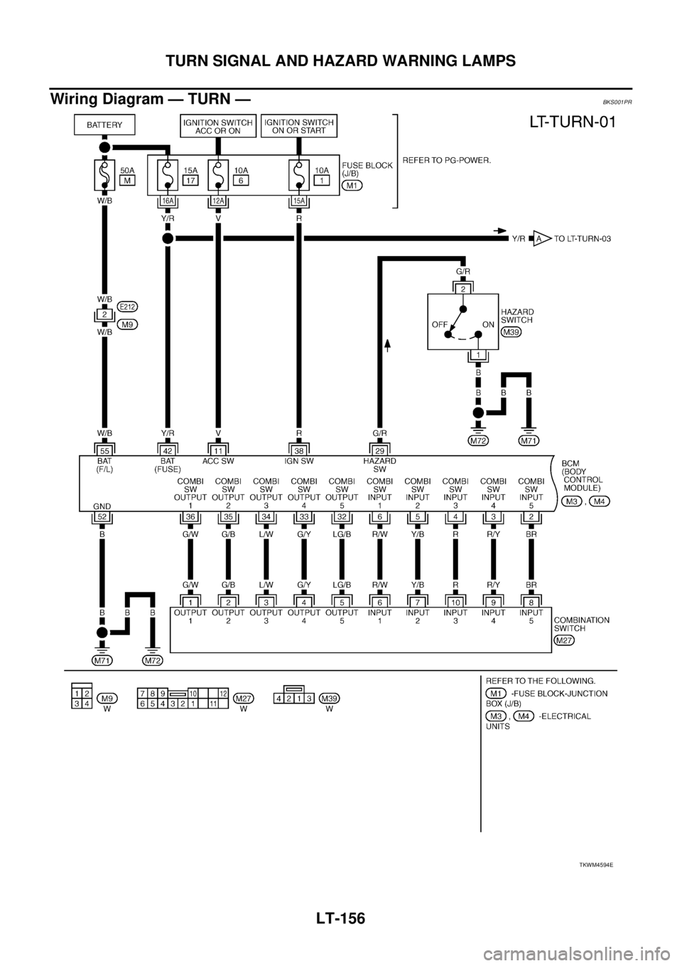
LT-156
TURN SIGNAL AND HAZARD WARNING LAMPS
Wiring Diagram — TURN —BKS001PR
TKWM4594E
Page 2849 of 3502
TURN SIGNAL AND HAZARD WARNING LAMPS
LT-161
C
D
E
F
G
H
I
J
L
MA
B
LT
Preliminary CheckBKS001PU
CHECK POWER SUPPLY AND GROUND CIRCUIT
1. CHECK FUSES AND FUSIBLE LINK
Check for blown fuses and fusible link.
Refer to LT-156, "Wiring Diagram — TURN —" .
OK or NG
OK >> GO TO 2.
NG >> If fuse or fusible link is blown, be sure to eliminate cause of malfunction before installing new fuse
or fusible link. Refer to PG-3, "
POWER SUPPLY ROUTING CIRCUIT" .
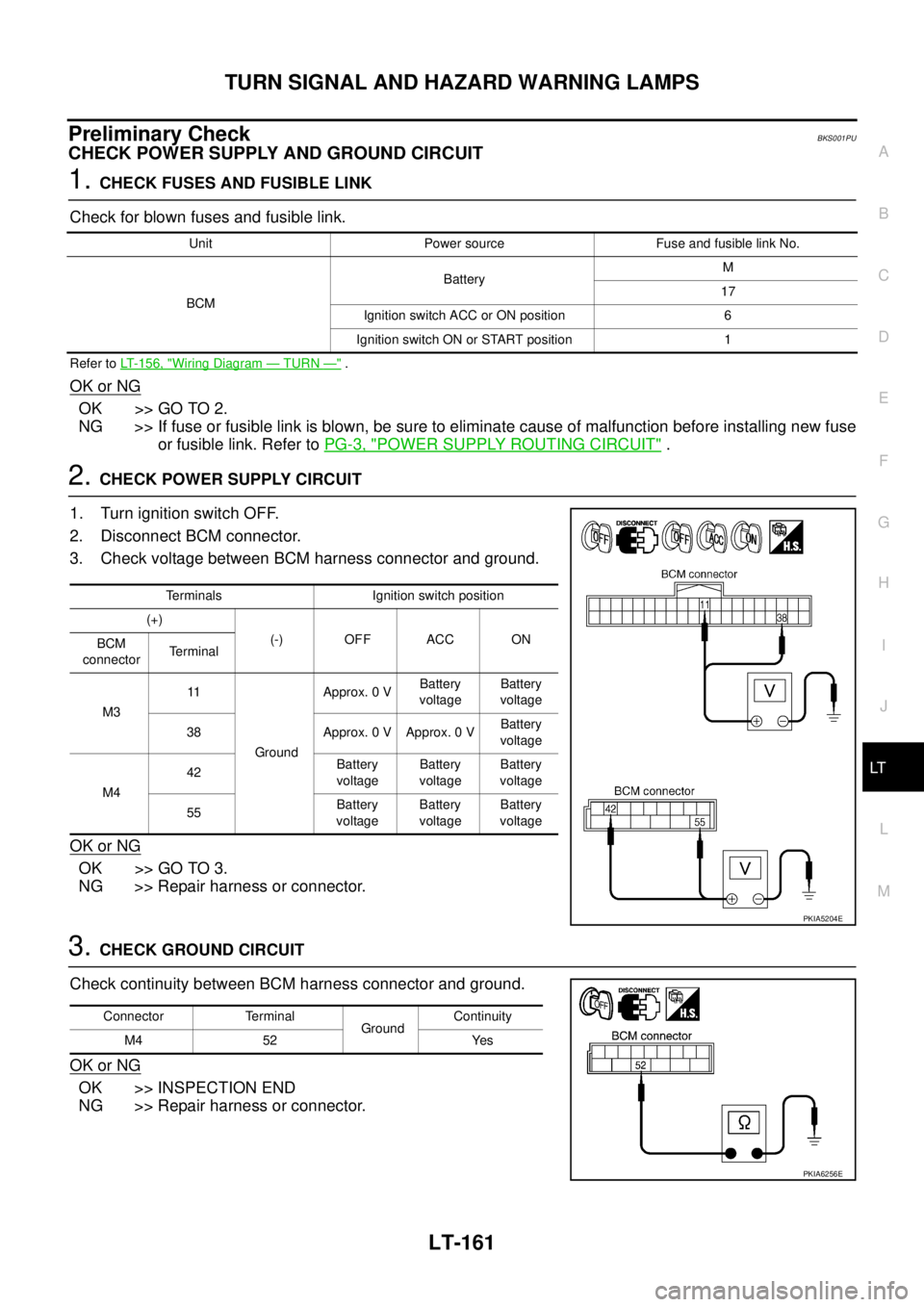
2. CHECK POWER SUPPLY CIRCUIT
1. Turn ignition switch OFF.
2. Disconnect BCM connector.
3. Check voltage between BCM harness connector and ground.
OK or NG
OK >> GO TO 3.
NG >> Repair harness or connector.
3. CHECK GROUND CIRCUIT
Check continuity between BCM harness connector and ground.
OK or NG
OK >> INSPECTION END
NG >> Repair harness or connector.
Unit Power source Fuse and fusible link No.
BCMBatteryM
17
Ignition switch ACC or ON position 6
Ignition switch ON or START position 1
Terminals Ignition switch position
(+)
(-) OFF ACC ON
BCM
connectorTerminal
M311
GroundApprox. 0 VBattery
voltageBattery
voltage
38 Approx. 0 V Approx. 0 VBattery
voltage
M442Battery
voltageBattery
voltageBattery
voltage
55Battery
voltageBattery
voltageBattery
voltage
PKIA5204E
Connector Terminal
GroundContinuity
M4 52 Yes
PKIA6256E
Page 2866 of 3502
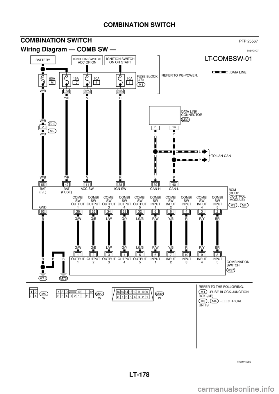
LT-178
COMBINATION SWITCH
COMBINATION SWITCHPFP:25567
Wiring Diagram — COMB SW —BKS001Q7
TKWM4596E
Page 2878 of 3502
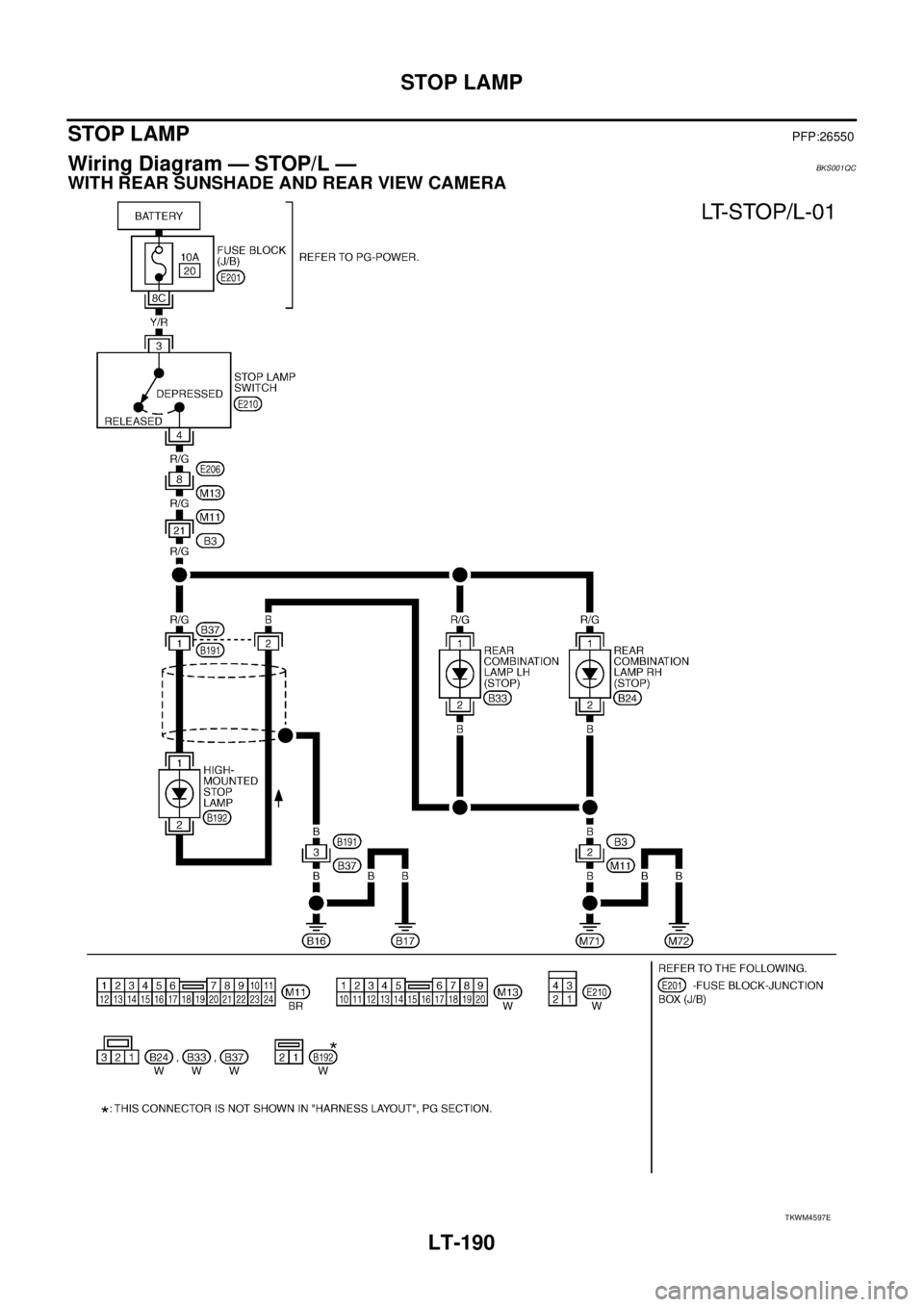
LT-190
STOP LAMP
STOP LAMPPFP:26550
Wiring Diagram — STOP/L —BKS001QC
WITH REAR SUNSHADE AND REAR VIEW CAMERA
TKWM4597E
Page 2881 of 3502
BACK-UP LAMP
LT-193
C
D
E
F
G
H
I
J
L
MA
B
LT
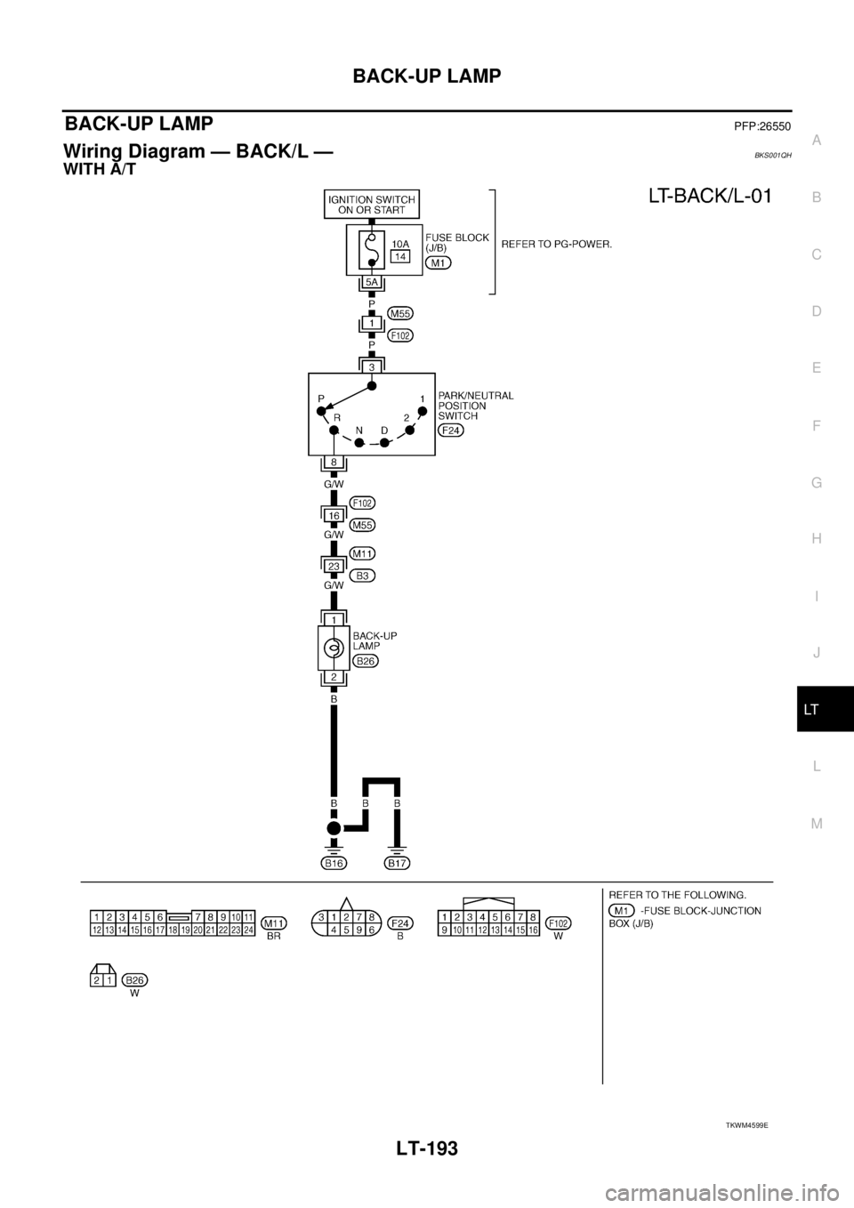
BACK-UP LAMPPFP:26550
Wiring Diagram — BACK/L — BKS001QH
WITH A/T
TKWM4599E
Page 2888 of 3502
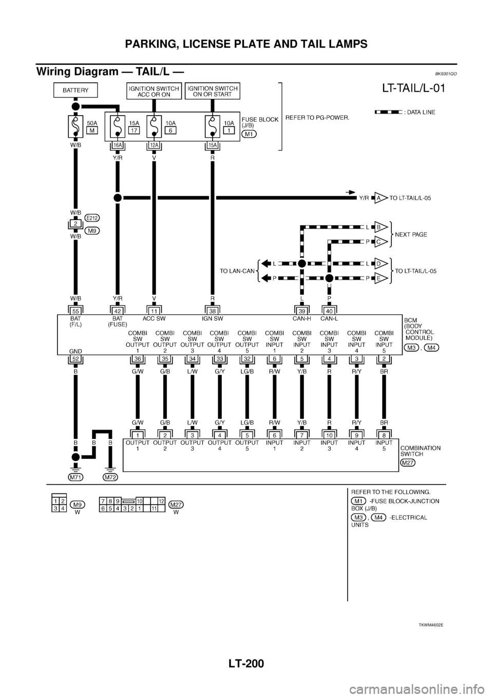
LT-200
PARKING, LICENSE PLATE AND TAIL LAMPS
Wiring Diagram — TAIL/L —BKS001QO
TKWM4602E