Page 3123 of 3502

STEERING WHEEL
PS-9
C
D
E
F
H
I
J
K
L
MA
B
PS
STEERING WHEELPFP:48430
On-Vehicle Inspection and ServiceBGS0003S
CHECKING CONDITION OF INSTALLATION
�Check installation conditions of steering gear assembly, front suspension assembly, axle and steering col-
umn assembly.
�Check if movement exists when steering wheel is moved up and down, to the left and right and to the axial
direction.
�Check steering gear assembly mounting nut and bolts for looseness. Refer to PS-17, "COMPONENTS" .
CHECKING STEERING WHEEL PLAY
�Turn steering wheel so that front wheels come to the straight-ahead position. Start engine and lightly turn
steering wheel to the left and right until front wheels start to move. Measure steering wheel movement on
the outer circumference.
�When the measurement value is outside the standard value, check backlash for each joint of steering col-
umn assembly and installation condition of power steering gear assembly.
CHECKING NEUTRAL POSITION STEERING WHEEL
�Make sure that steering gear assembly, steering column and steering wheel are installed in the correct
position.
�Perform neutral position inspection after wheel alignment. Refer to FSU-5, "Wheel Alignment Inspection" .
�Set vehicle to the straight-ahead position and confirm steering wheel is in the neutral position.
�Loosen outer socket lock nut and turn inner socket to left and right equally to make fine adjustments if
steering wheel is not in the neutral position.
CHECKING STEERING WHEEL TURNING FORCE
1. Park vehicle on a level and dry surface, set parking brake.
2. Start engine.
3. Bring power steering fluid up to adequate operating temperature. [Make sure temperature of fluid is
approximately 50 to 80°C (122 to 176°F).]
NOTE:
Tires need to be inflated normal pressure.
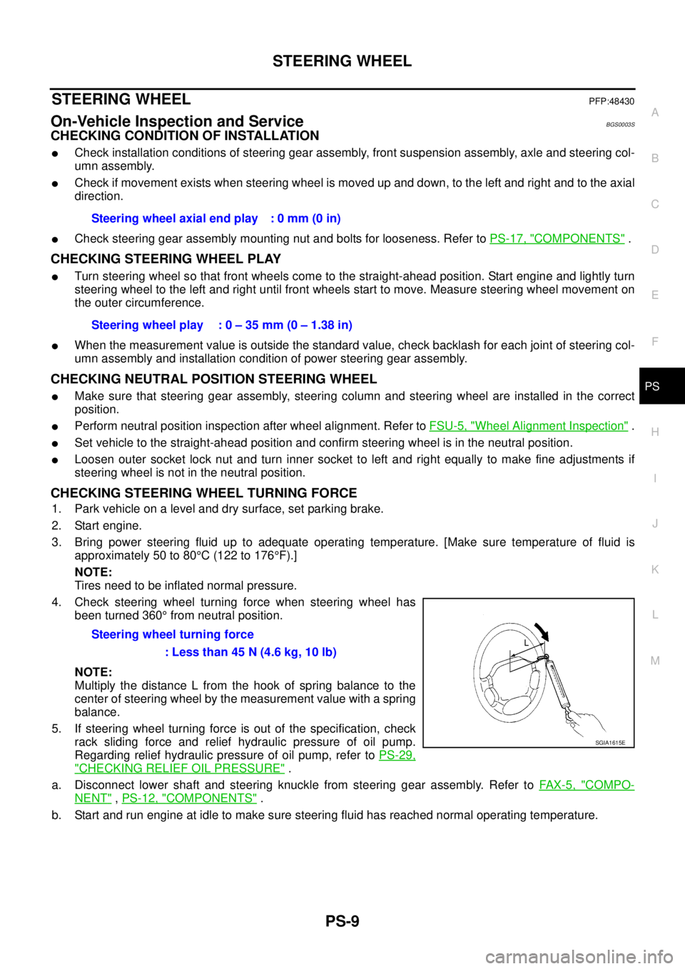
4. Check steering wheel turning force when steering wheel has
been turned 360° from neutral position.
NOTE:
Multiply the distance L from the hook of spring balance to the
center of steering wheel by the measurement value with a spring
balance.
5. If steering wheel turning force is out of the specification, check
rack sliding force and relief hydraulic pressure of oil pump.
Regarding relief hydraulic pressure of oil pump, refer to PS-29,
"CHECKING RELIEF OIL PRESSURE" .
a. Disconnect lower shaft and steering knuckle from steering gear assembly. Refer to FAX-5, "
COMPO-
NENT" , PS-12, "COMPONENTS" .
b. Start and run engine at idle to make sure steering fluid has reached normal operating temperature.Steering wheel axial end play : 0 mm (0 in)
Steering wheel play : 0 – 35 mm (0 – 1.38 in)
Steering wheel turning force
: Less than 45 N (4.6 kg, 10 lb)
SGIA1615E
Page 3143 of 3502

POWER STEERING OIL PUMP
PS-29
C
D
E
F
H
I
J
K
L
MA
B
PS
POWER STEERING OIL PUMPPFP:49110
On-Vehicle Inspection and ServiceBGS0003Y
CHECKING RELIEF OIL PRESSURE
CAUTION:
Make sure that belt tension is normal before starting the following procedure.
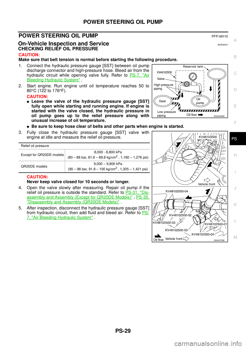
1. Connect the hydraulic pressure gauge [SST] between oil pump
discharge connector and high-pressure hose. Bleed air from the
hydraulic circuit while opening valve fully. Refer to PS-7, "
Air
Bleeding Hydraulic System" .
2. Start engine. Run engine until oil temperature reaches 50 to
80°C (122 to 176°F).
CAUTION:
�Leave the valve of the hydraulic pressure gauge [SST]
fully open while starting and running engine. If engine is
started with the valve closed, the hydraulic pressure in
oil pump goes up to the relief pressure along with
unusual increase of oil temperature.
�Be sure to keep hose clear of belts and other parts when engine is started.
3. Fully close the hydraulic pressure gauge [SST] valve with
engine at idle and measure the relief oil pressure.
CAUTION:
Never keep valve closed for 10 seconds or longer.
4. Open the valve slowly after measuring. Repair oil pump if the
relief oil pressure is outside the standard. Refer to PS-31, "
Dis-
assembly and Assembly (Except for QR20DE Models)" , PS-35,
"Disassembly and Assembly (QR20DE Models)" .
5. After inspection, disconnect the hydraulic pressure gauge [SST]
from hydraulic circuit, then add fluid and bleed air. Refer to PS-
7, "Air Bleeding Hydraulic System" .
Relief oil pressure
Except for QR20DE models8,000 - 8,800 kPa
(80 – 88 bar, 81.6 – 89.8 kg/cm
2 , 1,160 – 1,276 psi)
QR20DE models9,000 – 9,800 kPa
(90 – 98 bar, 91.8 – 100 kg/cm
2 , 1,305 – 1,421 psi)
SGIA0364E
SGIA0726E
Page 3156 of 3502
PS-42
SERVICE DATA AND SPECIFICATIONS (SDS)
SERVICE DATA AND SPECIFICATIONS (SDS)PFP:00030
Steering WheelBGS00043
Steering AngleBGS00044
Steering ColumnBGS00045
STEERING COLUMN LENGTH
TILT MECHANISM OPERATING RANGE
Steering wheel axial end play 0 mm (0 in)
Steering wheel play 0 – 35 mm (0 – 1.38 in)
Steering wheel turning force Less than 45 N (4.6 kg, 10 lb)
Tire size 205/65R16 215/55R17
Inner wheel
Degree minute (Decimal degree)Minimum 37°00′ (37.0°)33°00′ (33.0°)
Nominal 41°00′ (41.0°)37°00′ (37.0°)
Maximum 42°00′ (42.0°)38°00′ (38.0°)
Outer wheel
Degree minute (Decimal degree)Nominal 33°00′ (33.0°)31°00′ (31.0°)
Steering column length L 510.5 mm (20.10 in)
SGIA0986E
Tilt mechanism operating range L 31.5 mm (1.240 in)
SGIA1616E
Page 3157 of 3502

SERVICE DATA AND SPECIFICATIONS (SDS)
PS-43
C
D
E
F
H
I
J
K
L
MA
B
PS
Steering GearBGS00046
STEERING OUTER SOCKET AND INNER SOCKET
RACK STROKE
RACK SLIDING FORCE
Oil PumpBGS00048
Steering FluidBGS00049
Steering gear typePR26AM
Outer socketSwinging torque 0.3 – 2.9 N·m (0.03 – 0.29 kg-m, 3 – 25 in-lb)
Measurement on spring balance
�Measuring point at cotter pin hole of stud4.84 – 46.7 N (0.5 – 4.8 kg, 1 – 10 lb)
Rotating torque 0.3 – 2.9 N·m (0.03 – 0.29 kg-m, 3 – 25 in-lb)
Axial end play 0.5 mm (0.020 in) or less
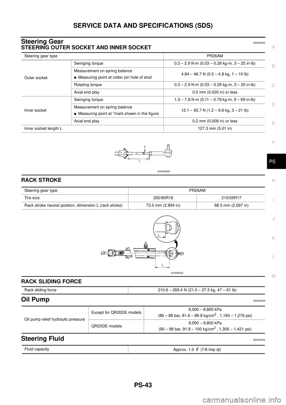
Inner socketSwinging torque 1.0 – 7.8 N·m (0.11 – 0.79 kg-m, 9 – 69 in-lb)
Measurement on spring balance
�Measuring point at *mark shown in the figure12.1 – 93.7 N (1.2 – 9.6 kg, 3 – 21 lb)
Axial end play 0.2 mm (0.008 in) or less
Inner socket length L127.3 mm (5.01 in)
SGIA0950E
Steering gear typePR26AM
Tire size 205/65R16 215/55R17
Rack stroke neutral position, dimension L (rack stroke) 73.5 mm (2.894 in) 68.5 mm (2.697 in)
SGIA0629J
Rack sliding force 210.6 – 269.4 N (21.5 – 27.5 kg, 47 – 61 lb)
Oil pump relief hydraulic pressureExcept for QR20DE models8,000 – 8,800 kPa
(80 – 88 bar, 81.6 – 89.8 kg/cm
2 , 1,160 – 1,276 psi)
QR20DE models9,000 – 9,800 kPa
(90 – 98 bar, 91.8 – 100 kg/cm
2 , 1,305 – 1,421 psi)
Fluid capacity
Approx. 1.0 (7/8 Imp qt)
Page 3158 of 3502
PS-44
SERVICE DATA AND SPECIFICATIONS (SDS)
Page 3159 of 3502
RAX-1
REAR AXLE
D DRIVELINE/AXLE
CONTENTS
C
E
F
G
H
I
J
K
L
M
SECTION RAX
A
B
RAX
REAR AXLE
NOISE, VIBRATION AND HARSHNESS (NVH)
TROUBLESHOOTING ................................................ 2
NVH Troubleshooting Chart ..................................... 2
WHEEL HUB .............................................................. 3
On-Vehicle Inspection .............................................. 3WHEEL BEARING INSPECTION ......................... 3
Removal and Installation .......................................... 3
COMPONENT ....................................................... 3
REMOVAL ............................................................. 3
INSPECTION AFTER REMOVAL ......................... 4
INSTALLATION ..................................................... 4
SERVICE DATA AND SPECIFICATIONS (SDS) ........ 6
Wheel Bearing .......................................................... 6
Page 3164 of 3502
RAX-6
SERVICE DATA AND SPECIFICATIONS (SDS)
SERVICE DATA AND SPECIFICATIONS (SDS)PFP:00030
Wheel BearingBDS00080
Axial end play0.05 mm (0.002 in) or less
Page 3165 of 3502

RF-1
ROOF
I BODY
CONTENTS
C
D
E
F
G
H
J
K
L
M
SECTION RF
A
B
RF
ROOF
PRECAUTIONS .......................................................... 2
Precautions for Supplemental Restraint System
(SRS) “AIR BAG” and “SEAT BELT PRE-TEN-
SIONER” .................................................................. 2
Precautions .............................................................. 2
PREPARATION ........................................................... 3
Commercial Service Tools ........................................ 3
SQUEAK AND RATTLE TROUBLE DIAGNOSES ..... 4
Work Flow ................................................................ 4
CUSTOMER INTERVIEW ..................................... 4
DUPLICATE THE NOISE AND TEST DRIVE ....... 5
CHECK RELATED SERVICE BULLETINS ........... 5
LOCATE THE NOISE AND IDENTIFY THE
ROOT CAUSE ...................................................... 5
REPAIR THE CAUSE ........................................... 5
CONFIRM THE REPAIR ....................................... 6
Generic Squeak and Rattle Troubleshooting ........... 6
INSTRUMENT PANEL .......................................... 6
CENTER CONSOLE ............................................. 6
DOORS ................................................................. 6
TRUNK .................................................................. 7
SUNROOF/HEADLINING ..................................... 7
SEATS ................................................................... 7
UNDERHOOD ....................................................... 7
Diagnostic Worksheet .............................................. 8
SUNROOF ................................................................ 10
Component Parts and Harness Connector Location ... 10
System Description ................................................. 11
TILT UP / SLIDE CLOSE OPERATION ................ 11
TILT DOWN / SLIDE OPEN OPERATION ........... 11AUTO OPERATION ............................................. 11
TIMER FUNCTION .............................................. 11
ANTI-PINCH FUNCTION .................................... 11
MEMORY RESET PROCEDURE ....................... 12
INITIALIZATION PROCEDURE .......................... 12
Wiring Diagram — SROOF — ................................ 13
Terminals and Reference Value for BCM ............... 14
Terminals and Reference Value for Sunroof Motor
Assembly ................................................................ 14
Work Flow ............................................................... 15
Trouble Diagnosis Chart by Symptom .................... 15
Check BCM Power Supply and Ground Circuit ...... 15
Check Sunroof Motor Assembly Power Supply and
Ground Circuit ........................................................ 16
Check Sunroof Switch System ............................... 17
Check Driver Side Door Switch .............................. 19
Wind Deflector Inspection ....................................... 21
Link and Wire Assembly ......................................... 21
Fitting Adjustment ................................................... 21
LID WEATHERSTRIP OVERLAP ADJUST-
MENT AND SURFACE FLASHNESS ADJUST-
MENT .................................................................. 22
Removal and Installation ........................................ 22
SUNROOF UNIT ASSEMBLY ............................. 24
GLASS LID .......................................................... 25
WEATHERSTRIP OF GLASS LID ....................... 26
SUNSHADE ........................................................ 26
WIND DEFLECTOR ............................................ 26
SUNROOF MOTOR ASSEMBLY ........................ 27
LINK ASSEMBLY AND WIRE ASSEMBLY ......... 27