Page 3148 of 3502
PS-34
POWER STEERING OIL PUMP
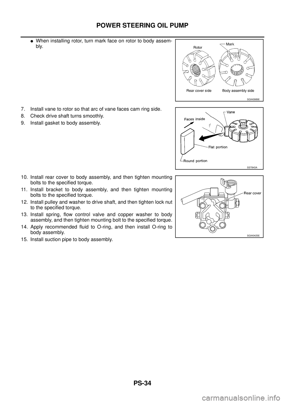
�When installing rotor, turn mark face on rotor to body assem-
bly.
7. Install vane to rotor so that arc of vane faces cam ring side.
8. Check drive shaft turns smoothly.
9. Install gasket to body assembly.
10. Install rear cover to body assembly, and then tighten mounting
bolts to the specified torque.
11. Install bracket to body assembly, and then tighten mounting
bolts to the specified torque.
12. Install pulley and washer to drive shaft, and then tighten lock nut
to the specified torque.
13. Install spring, flow control valve and copper washer to body
assembly, and then tighten mounting bolt to the specified torque.
14. Apply recommended fluid to O-ring, and then install O-ring to
body assembly.
15. Install suction pipe to body assembly.
SGIA0989E
SST843A
SGIA0425E
Page 3153 of 3502
HYDRAULIC LINE
PS-39
C
D
E
F
H
I
J
K
L
MA
B
PS
HYDRAULIC LINEPFP:49721
Removal and InstallationBGS00041
COMPONENTS (EXCEPT FOR QR20DE MODELS)
1. Reservoir tank 2. Reservoir tank bracket 3. Suction hose
4. Oil pump assembly 5. High pressure hose 6. Steering gear assembly
7. Low pressure piping 8. High pressure piping 9. O-ring
10. Clamp 11. Copper washer 12. Eye-joint (assembled to high pres-
sure side hose)
13. Pressure sensor 14. Eye-bolt
Refer to GI-10, "
Components" , and the followings for the symbols in the figure.
: Apply power steering fluid.
SGIA1621E
Page 3154 of 3502
PS-40
HYDRAULIC LINE
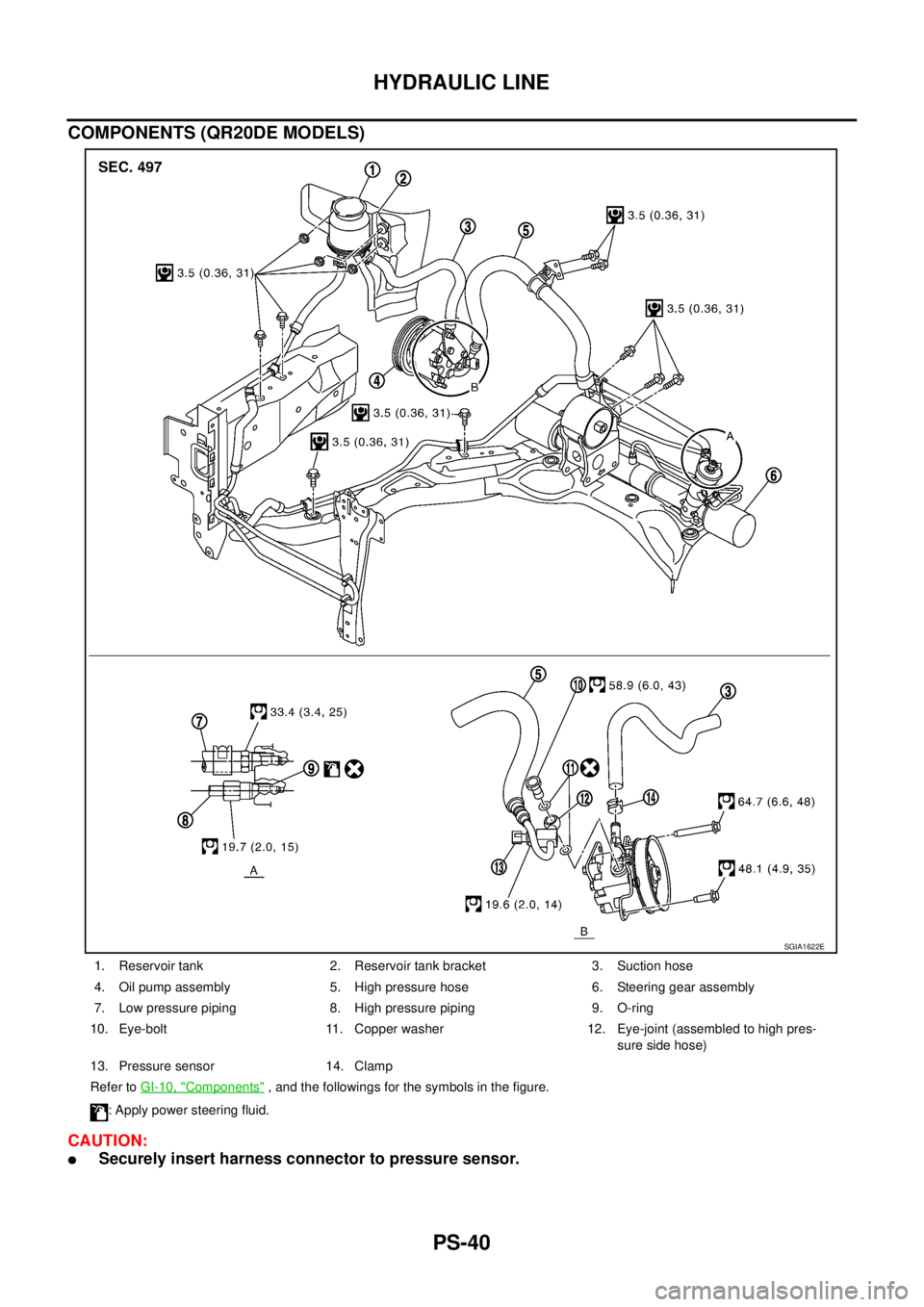
COMPONENTS (QR20DE MODELS)
CAUTION:
�Securely insert harness connector to pressure sensor.
1. Reservoir tank 2. Reservoir tank bracket 3. Suction hose
4. Oil pump assembly 5. High pressure hose 6. Steering gear assembly
7. Low pressure piping 8. High pressure piping 9. O-ring
10. Eye-bolt 11. Copper washer 12. Eye-joint (assembled to high pres-
sure side hose)
13. Pressure sensor 14. Clamp
Refer to GI-10, "
Components" , and the followings for the symbols in the figure.
: Apply power steering fluid.
SGIA1622E
Page 3472 of 3502

WW-34
FRONT WIPER AND WASHER SYSTEM
Removal and Installation of Front Wiper Arms, Adjustment of Wiper Arms Stop
Location
BKS003W6
REMOVAL
1. Turn front wiper switch ON to operate wiper motor, then turn front wiper switch OFF (auto stop).
2. Open hood, remove front wiper arm caps, and remove front wiper arm nuts.
3. Raise front wiper arms, and remove front wiper arms from the vehicle.
INSTALLATION
1. Clean up the pivot area as shown in the figure. This will reduce
possibility of front wiper arm nuts looseness.
2. Prior to front wiper arms installation, turn front wiper switch ON
to operate wiper motor, and then turn front wiper switch OFF
(auto stop).
3. Lift the blade up and then set it down onto windshield glass sur-
face to set the blade center to clearance “L1” & “L2” immedi-
ately.
4. Tighten front wiper arm nuts to specified torque.
5. Spray washer fluid. Turn on wiper switch ON to operate wiper
motor, and then turn front wiper switch OFF (auto stop).
6. Make sure that wiper blades stop within clearance “L1” & “L2”.
7. Install wiper arm caps.
Removal and Installation of Front Wiper Drive AssemblyBKS003W7
REMOVAL
1. Remove front wiper arms. Refer to WW-34, "REMOVAL" .
2. Remove cowl top covers (RH, LH). Refer to EI-21, "
COWL TOP" .
3. Disconnect wiper motor connector (1).
4. Remove front wiper drive assembly mounting bolts (A), and
remove front wiper drive assembly (2) from the vehicle.
SEL024J
Front wiper arm nuts : 23.5 N·m (2.4 kg-m, 17 ft-lb)
Clearance “L1” : 27.6 ± 7.5 mm (1.087 - 0.295 in)
Clearance “L2” : 36.1 ± 7.5 mm (1.421 - 0.295 in)
PKIA9951E
PKID0309E
Page 3495 of 3502
HEADLAMP WASHER
WW-57
C
D
E
F
G
H
I
J
L
MA
B
WW
Removal and Installation of Headlamp Washer NozzleBKS002EX
REMOVAL
1. Pull out headlamp washer nozzle from a bumper, remove pawl
(A), and remove headlamp washer nozzle cover (1).
2. Remove undercover one.
3. Remove fender protector. Refer to EI-23, "
FENDER PROTEC-
TOR" .
4. Remove front bumper. Refer to EI-14, "
FRONT BUMPER" .
5. Remove headlamp washer tube (1). Refer to WW-58, "
Removal
and Installation of Headlamp Washer Tube Connector" .
6. Removal headlamp washer nozzle retainer (A).
7. Removal headlamp washer nozzle bracket (2).
8. Remove headlamp washer nozzle assembly (3).
�The check valve is installed in headlamp washer nozzle
assembly.
�The check valve prevents backflow of washer fluid.
INSTALLATION
Installation is the reverse order of removal.
CAUTION:
When installing nozzle, there should be no packing twist, etc.
AdjustmentBKS002EY
PKIC9877E
PKIC9878E
PKIC9879E
a: 45° ±3°
b: 46° ±3°
c: 14° ±3°
d: 11° ±3°

1. Reservoir tank 2. Reservoir tank bracket 3. Suction h")
, and remove headl")