Page 1013 of 3502
INDEX FOR DTC
CVT-7
D
E
F
G
H
I
J
K
L
MA
B
CVT
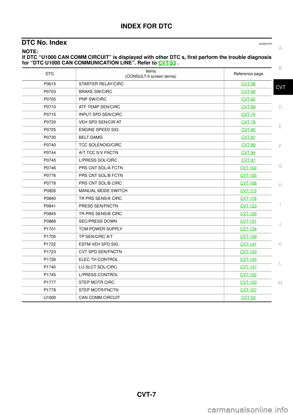
DTC No. Index BCS001FN
NOTE:
If DTC “U1000 CAN COMM CIRCUIT” is displayed with other DTC s, first perform the trouble diagnosis
for “DTC U1000 CAN COMMUNICATION LINE”. Refer to CVT-53
.
DTCItems
(CONSULT-II screen terms)Reference page
P0615 STARTER RELAY/CIRCCVT-56
P0703 BRAKE SW/CIRCCVT-60
P0705 PNP SW/CIRCCVT-62
P0710 ATF TEMP SEN/CIRCCVT-69
P0715 INPUT SPD SEN/CIRCCVT-74
P0720 VEH SPD SEN/CIR ATCVT-79
P0725 ENGINE SPEED SIGCVT-85
P0730 BELT DAMGCVT-87
P0740 TCC SOLENOID/CIRCCVT-89
P0744 A/T TCC S/V FNCTNCVT-94
P0745 L/PRESS SOL/CIRCCVT-97
P0746 PRS CNT SOL/A FCTNCVT-102
P0776 PRS CNT SOL/B FCTNCVT-105
P0778 PRS CNT SOL/B CIRCCVT-108
P0826 MANUAL MODE SWITCHCVT-113
P0840 TR PRS SENS/A CIRCCVT-118
P0841 PRESS SEN/FNCTNCVT-123
P0845 TR PRS SENS/B CIRCCVT-126
P0868 SEC/PRESS DOWNCVT-131
P1701 TCM-POWER SUPPLYCVT-134
P1705 TP SEN/CIRC A/TCVT-139
P1722 ESTM VEH SPD SIGCVT-141
P1723 CVT SPD SEN/FNCTNCVT-143
P1726 ELEC TH CONTROLCVT-145
P1740 LU-SLCT SOL/CIRCCVT-147
P1745 L/PRESS CONTROLCVT-152
P1777 STEP MOTR CIRCCVT-153
P1778 STEP MOTR/FNCTNCVT-157
U1000 CAN COMM CIRCUITCVT-53
Page 1019 of 3502
CVT FLUID
CVT-13
D
E
F
G
H
I
J
K
L
MA
B
CVT
CVT FLUIDPFP:KLE50
Checking CVT FluidBCS001FX
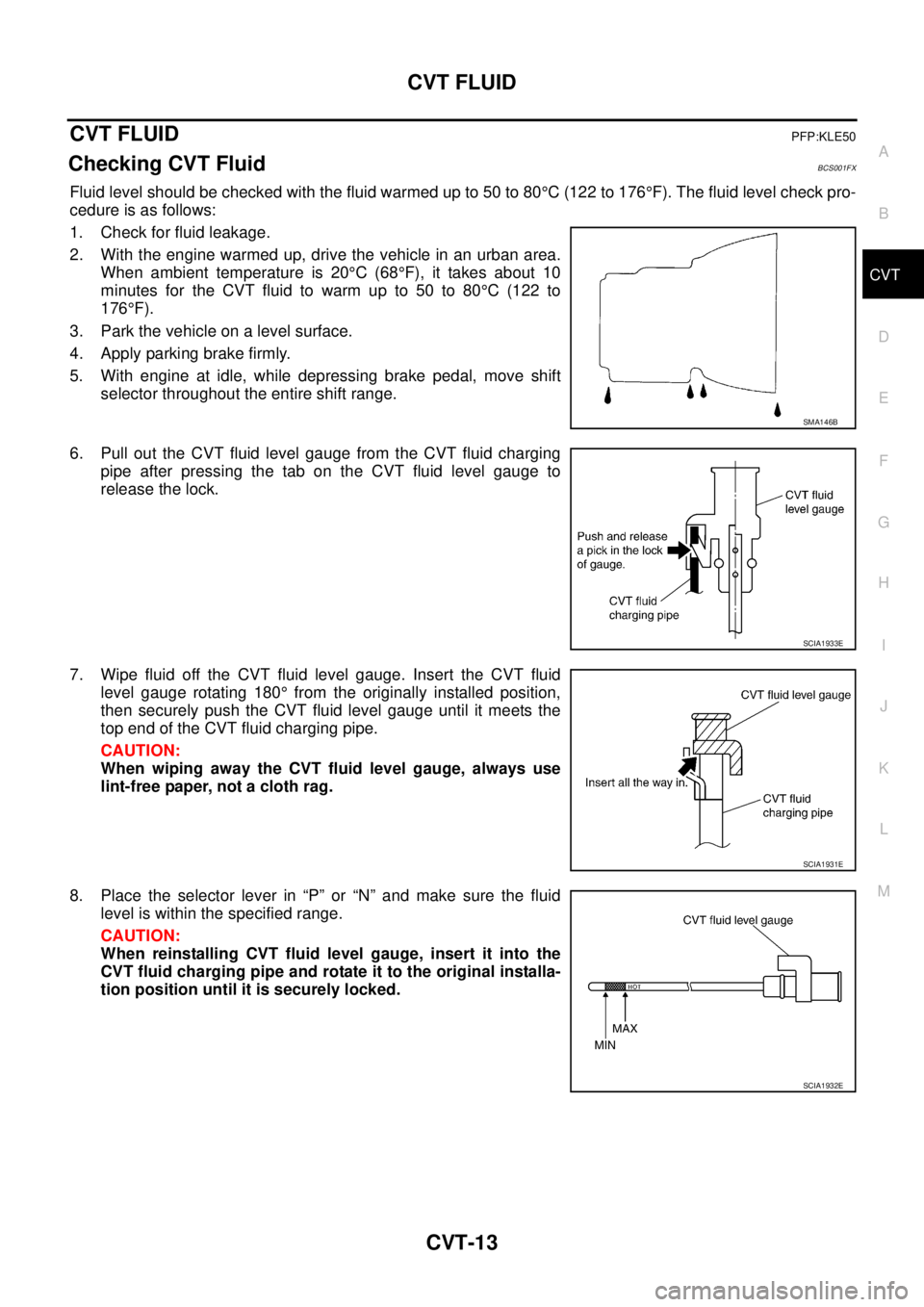
Fluid level should be checked with the fluid warmed up to 50 to 80°C (122 to 176°F). The fluid level check pro-
cedure is as follows:
1. Check for fluid leakage.
2. With the engine warmed up, drive the vehicle in an urban area.
When ambient temperature is 20°C (68°F), it takes about 10
minutes for the CVT fluid to warm up to 50 to 80°C (122 to
176°F).
3. Park the vehicle on a level surface.
4. Apply parking brake firmly.
5. With engine at idle, while depressing brake pedal, move shift
selector throughout the entire shift range.
6. Pull out the CVT fluid level gauge from the CVT fluid charging
pipe after pressing the tab on the CVT fluid level gauge to
release the lock.
7. Wipe fluid off the CVT fluid level gauge. Insert the CVT fluid
level gauge rotating 180° from the originally installed position,
then securely push the CVT fluid level gauge until it meets the
top end of the CVT fluid charging pipe.
CAUTION:
When wiping away the CVT fluid level gauge, always use
lint-free paper, not a cloth rag.
8. Place the selector lever in “P” or “N” and make sure the fluid
level is within the specified range.
CAUTION:
When reinstalling CVT fluid level gauge, insert it into the
CVT fluid charging pipe and rotate it to the original installa-
tion position until it is securely locked.
SMA146B
SCIA1933E
SCIA1931E
SCIA1932E
Page 1020 of 3502
CVT-14
CVT FLUID
9. Check CVT fluid condition.
�If CVT fluid is very dark or smells burned, check operation of
CVT. Flush cooling system after repair of CVT.
�If CVT fluid contains frictional material (clutches, bands, etc.),
replace radiator and flush cooler line using cleaning solvent
and compressed air after repair of CVT. Refer to CO-37,
"RADIATOR" .
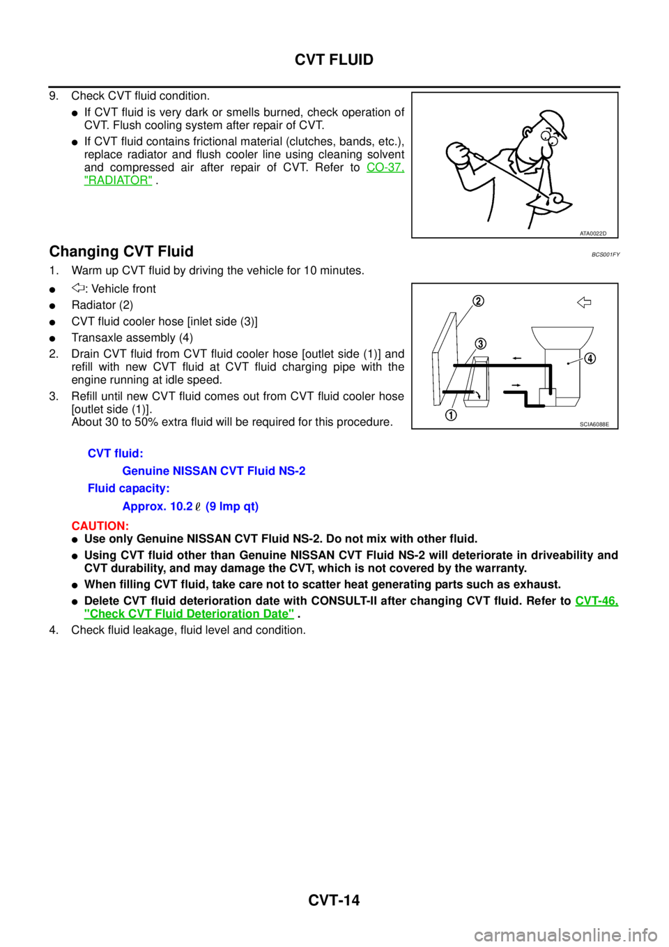
Changing CVT FluidBCS001FY
1. Warm up CVT fluid by driving the vehicle for 10 minutes.
�: Vehicle front
�Radiator (2)
�CVT fluid cooler hose [inlet side (3)]
�Transaxle assembly (4)
2. Drain CVT fluid from CVT fluid cooler hose [outlet side (1)] and
refill with new CVT fluid at CVT fluid charging pipe with the
engine running at idle speed.
3. Refill until new CVT fluid comes out from CVT fluid cooler hose
[outlet side (1)].
About 30 to 50% extra fluid will be required for this procedure.
CAUTION:
�Use only Genuine NISSAN CVT Fluid NS-2. Do not mix with other fluid.
�Using CVT fluid other than Genuine NISSAN CVT Fluid NS-2 will deteriorate in driveability and
CVT durability, and may damage the CVT, which is not covered by the warranty.
�When filling CVT fluid, take care not to scatter heat generating parts such as exhaust.
�Delete CVT fluid deterioration date with CONSULT-II after changing CVT fluid. Refer to CVT-46,
"Check CVT Fluid Deterioration Date" .
4. Check fluid leakage, fluid level and condition.
ATA0022D
CVT fluid:
Genuine NISSAN CVT Fluid NS-2
Fluid capacity:
Approx. 10.2 (9 lmp qt)
SCIA6088E
Page 1024 of 3502
CVT-18
CVT SYSTEM
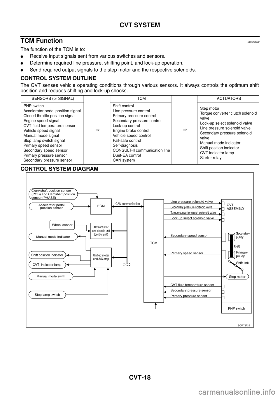
TCM FunctionBCS001G2
The function of the TCM is to:
�Receive input signals sent from various switches and sensors.
�Determine required line pressure, shifting point, and lock-up operation.
�Send required output signals to the step motor and the respective solenoids.
CONTROL SYSTEM OUTLINE
The CVT senses vehicle operating conditions through various sensors. It always controls the optimum shift
position and reduces shifting and lock-up shocks.
CONTROL SYSTEM DIAGRAM
SENSORS (or SIGNAL)
�TCM
�ACTUATORS
PNP switch
Accelerator pedal position signal
Closed throttle position signal
Engine speed signal
CVT fluid temperature sensor
Vehicle speed signal
Manual mode signal
Stop lamp switch signal
Primary speed sensor
Secondary speed sensor
Primary pressure sensor
Secondary pressure sensorShift control
Line pressure control
Primary pressure control
Secondary pressure control
Lock-up control
Engine brake control
Vehicle speed control
Fail-safe control
Self-diagnosis
CONSULT-II communication line
Duet-EA control
CAN systemSte p mo tor
Torque converter clutch solenoid
valve
Lock-up select solenoid valve
Line pressure solenoid valve
Secondary pressure solenoid
valve
Manual mode indicator
Shift position indicator
CVT indicator lamp
Starter relay
SCIA7872E
Page 1025 of 3502
CVT SYSTEM
CVT-19
D
E
F
G
H
I
J
K
L
MA
B
CVT
CAN CommunicationBCS001G3
SYSTEM DESCRIPTION
CAN (Controller Area Network) is a serial communication line for real time application. It is an on-vehicle mul-
tiplex communication line with high data communication speed and excellent error detection ability. Many elec-
tronic control units are equipped onto a vehicle, and each control unit shares information and links with other
control units during operation (not independent). In CAN communication, control units are connected with 2
communication lines (CAN-H line, CAN-L line) allowing a high rate of information transmission with less wiring.
Each control unit transmits/receives data but selectively reads required data only. For details, refer to LAN-49,
"CAN System Specification Chart" .
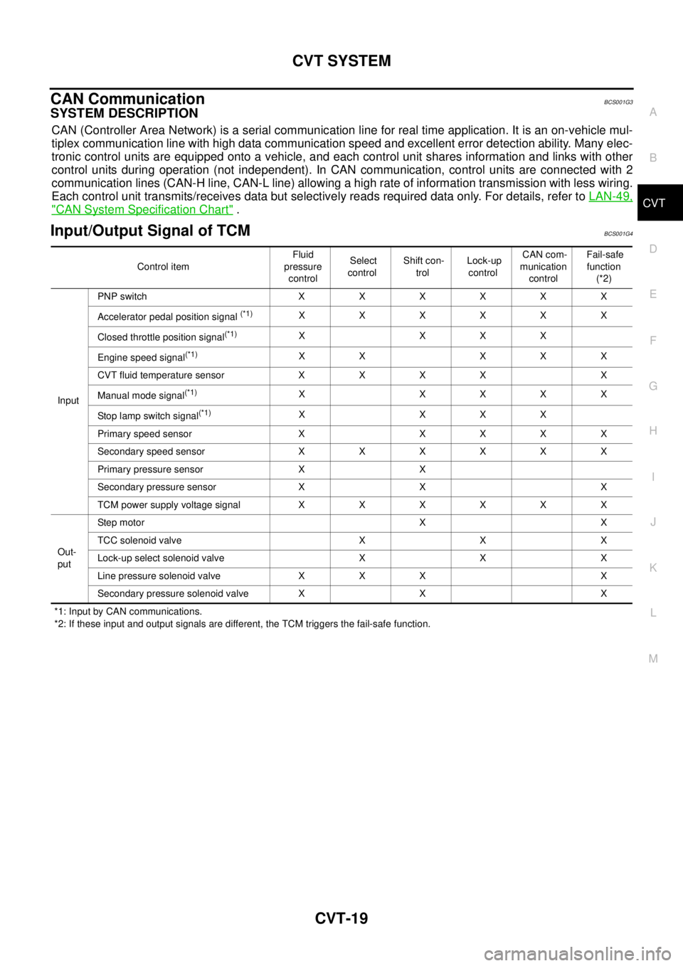
Input/Output Signal of TCMBCS001G4
*1: Input by CAN communications.
*2: If these input and output signals are different, the TCM triggers the fail-safe function. Control item Fluid
pressure
control Select
control Shift con-
trol Lock-up
control CAN com-
munication
control Fail-safe
function
(*2)
Input PNP switch XXXXXX
Accelerator pedal position signal
(*1)XXXXXX
Closed throttle position signal
(*1)XXXX
Engine speed signal
(*1)XX XXX
CVT fluid temperature sensor X X X X X
Manual mode signal
(*1)XXXXX
Stop lamp switch signal
(*1)XXXX
Primary speed sensor X X X X X
Secondary speed sensor X X X X X X
Primary pressure sensor X X
Secondary pressure sensor X X X
TCM power supply voltage signal X X X X X X
Out-
put Step motor X X
TCC solenoid valve X X X
Lock-up select solenoid valve X X X
Line pressure solenoid valve X X X X
Secondary pressure solenoid valve X X X
Page 1026 of 3502
CVT-20
CVT SYSTEM
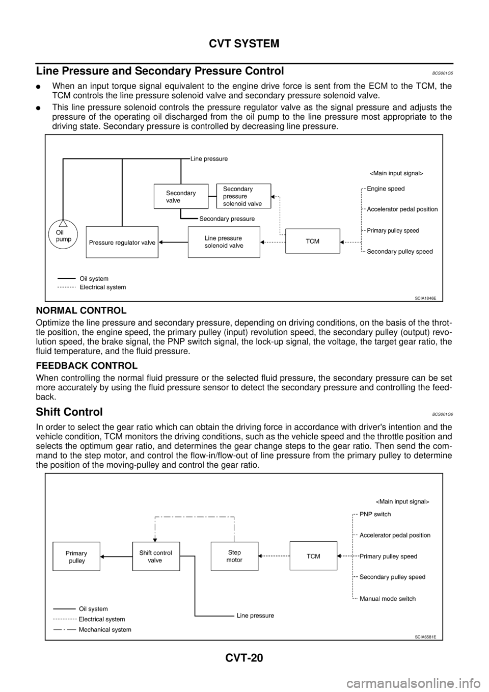
Line Pressure and Secondary Pressure ControlBCS001G5
�When an input torque signal equivalent to the engine drive force is sent from the ECM to the TCM, the
TCM controls the line pressure solenoid valve and secondary pressure solenoid valve.
�This line pressure solenoid controls the pressure regulator valve as the signal pressure and adjusts the
pressure of the operating oil discharged from the oil pump to the line pressure most appropriate to the
driving state. Secondary pressure is controlled by decreasing line pressure.
NORMAL CONTROL
Optimize the line pressure and secondary pressure, depending on driving conditions, on the basis of the throt-
tle position, the engine speed, the primary pulley (input) revolution speed, the secondary pulley (output) revo-
lution speed, the brake signal, the PNP switch signal, the lock-up signal, the voltage, the target gear ratio, the
fluid temperature, and the fluid pressure.
FEEDBACK CONTROL
When controlling the normal fluid pressure or the selected fluid pressure, the secondary pressure can be set
more accurately by using the fluid pressure sensor to detect the secondary pressure and controlling the feed-
back.
Shift ControlBCS001G6
In order to select the gear ratio which can obtain the driving force in accordance with driver's intention and the
vehicle condition, TCM monitors the driving conditions, such as the vehicle speed and the throttle position and
selects the optimum gear ratio, and determines the gear change steps to the gear ratio. Then send the com-
mand to the step motor, and control the flow-in/flow-out of line pressure from the primary pulley to determine
the position of the moving-pulley and control the gear ratio.
SCIA1846E
SCIA6581E
Page 1027 of 3502
CVT SYSTEM
CVT-21
D
E
F
G
H
I
J
K
L
MA
B
CVT
NOTE:
The gear ratio is set for every position separately.
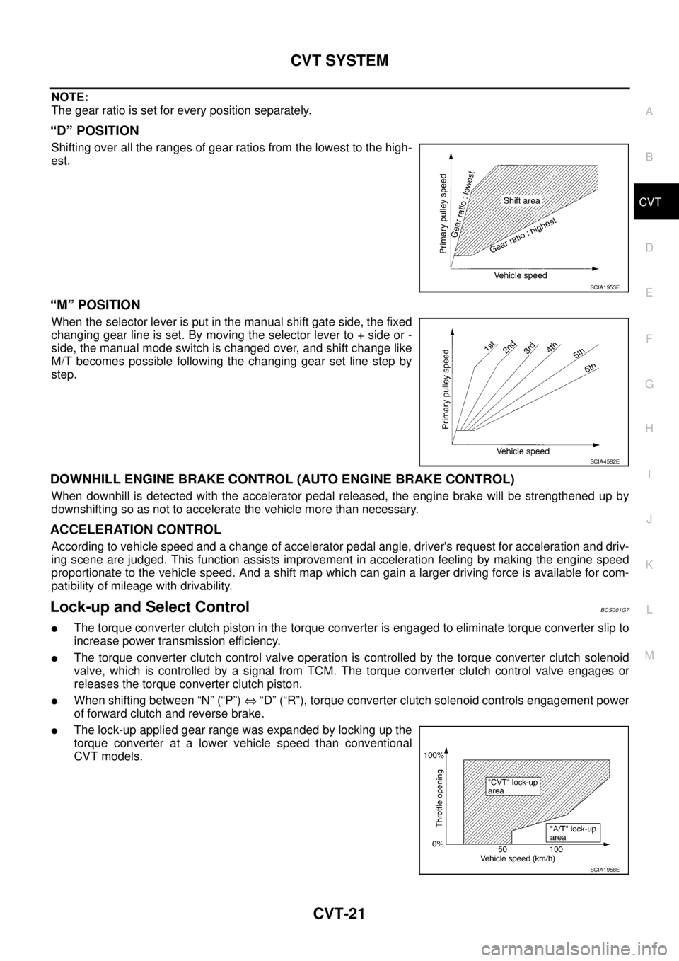
“D” POSITION
Shifting over all the ranges of gear ratios from the lowest to the high-
est.
“M” POSITION
When the selector lever is put in the manual shift gate side, the fixed
changing gear line is set. By moving the selector lever to + side or -
side, the manual mode switch is changed over, and shift change like
M/T becomes possible following the changing gear set line step by
step.
DOWNHILL ENGINE BRAKE CONTROL (AUTO ENGINE BRAKE CONTROL)
When downhill is detected with the accelerator pedal released, the engine brake will be strengthened up by
downshifting so as not to accelerate the vehicle more than necessary.
ACCELERATION CONTROL
According to vehicle speed and a change of accelerator pedal angle, driver's request for acceleration and driv-
ing scene are judged. This function assists improvement in acceleration feeling by making the engine speed
proportionate to the vehicle speed. And a shift map which can gain a larger driving force is available for com-
patibility of mileage with drivability.
Lock-up and Select ControlBCS001G7
�The torque converter clutch piston in the torque converter is engaged to eliminate torque converter slip to
increase power transmission efficiency.
�The torque converter clutch control valve operation is controlled by the torque converter clutch solenoid
valve, which is controlled by a signal from TCM. The torque converter clutch control valve engages or
releases the torque converter clutch piston.
�When shifting between “N” (“P”) ⇔ “D” (“R”), torque converter clutch solenoid controls engagement power
of forward clutch and reverse brake.
�The lock-up applied gear range was expanded by locking up the
torque converter at a lower vehicle speed than conventional
CVT models.
SCIA1953E
SCIA4582E
SCIA1958E
Page 1028 of 3502
CVT-22
CVT SYSTEM
TORQUE CONVERTER CLUTCH AND SELECT CONTROL VALVE CONTROL
Lock-up and Select Control System Diagram
Lock-up Released
In the lock-up released state, the torque converter clutch control valve is set into the unlocked state by the
torque converter clutch solenoid and the lock-up apply pressure is drained.
In this way, the torque converter clutch piston is not coupled.
Lock-up Applied
In the lock-up applied state, the torque converter clutch control valve is set into the locked state by the torque
converter clutch solenoid and lock-up apply pressure is generated.
In this way, the torque converter clutch piston is pressed and coupled.
Select Control
When shifting between “N” (“P”) ⇔ “D” (“R”), optimize the operating pressure on the basis of the throttle posi-
tion, the engine speed, and the secondary pulley (output) revolution speed to lessen the shift shock.
SCIA2374E