Page 3149 of 3502
BGS0004D
COMPONENTS
INSPECTION BEFORE DISASSEMBLY
Disassemble oil pump only when the following malfunc")
POWER STEERING OIL PUMP
PS-35
C
D
E
F
H
I
J
K
L
MA
B
PS
Disassembly and Assembly (QR20DE Models)BGS0004D
COMPONENTS
INSPECTION BEFORE DISASSEMBLY
Disassemble oil pump only when the following malfunctions occur.
�If oil leakage is found on oil pump.
�Oil pump pulley is damaged or deformed.
�Performance of oil pump is low.
DISASSEMBLY
NOTE:
Secure oil pump in a vise if necessary.
CAUTION:
Use copper plates when securing in a vise.
1. Remove rear bracket mounting bolts, and then remove rear bracket from rear cover.
2. Remove front bracket mounting bolts, and then remove front bracket from body assembly.
3. Remove rear cover mounting bolts, and then remove rear cover from body assembly.
4. Remove rear side plate from cartridge, and then remove Teflon ring and O-ring from rear side plate.
1. Rear bracket 2. Rear cover 3. Teflon ring
4. O-ring 5. Rear side plate 6. Rotor snap ring
7. Vane 8. Rotor 9. Cam ring
10. Cartridge 11. Front side plate 12. O-ring
13. Dowel pin 14. Flow control valve A 15. Flow control valve spring
16. Flow control valve B assembly 17. Body assembly 18. O-ring
19. Suction pipe 20. Oil seal 21. Front bracket
22. Pulley
Refer to GI-10, "
Components" , and the followings for the symbols in the figure.
: Apply power steering fluid.
: Apply multi-purpose grease.
SGIA1619E
Page 3150 of 3502

PS-36
POWER STEERING OIL PUMP
5. Remove rotor snap ring using a snap ring plier, and remove pul-
ley from body assembly.
CAUTION:
Remove pulley so as not to be damaged when removing
rotor snap ring.
6. Remove cartridge, front side plate, flow control valve A, flow
control valve spring, flow control valve B assembly from body
assembly.
CAUTION:
Do not drop and damage flow control valve A and flow con-
trol valve B assembly when removing.
7. Remove oil seal from body assembly.
8. Remove mounting bolts of suction pipe, and then remove suc-
tion pipe from body assembly.
9. Remove O-ring from body assembly.
INSPECTION AFTER DISASSEMBLY
Body Assembly and Rear Cover Inspection
Check body assembly and rear cover for internal damage. Replace rear cover if it is damaged. Replace oil
pump assembly if body assembly is damaged.
Cartridge Assembly Inspection
Check cam ring, rotor and vane for damage. Replace cartridge assembly if necessary.
Side Plate Inspection
Check side plate (front and rear) for damage. Side plate (front and rear) must be replaced as a set if they are
damaged.
Flow Control Valve Inspection
Check flow control valve A, flow control valve spring and flow control valve B assembly for damage. Replace if
there are.
SGIA0059E
SGIA0526E
Page 3151 of 3502
POWER STEERING OIL PUMP
PS-37
C
D
E
F
H
I
J
K
L
MA
B
PS
ASSEMBLY
NOTE:
Secure oil pump in a vise if necessary.
CAUTION:
Use copper plates when securing in a vise.
1. Apply recommended grease to oil seal lips. Apply recommended
fluid to around oil seal, and then install oil seal to body assembly
using the drift [SST].
2. If dowel pin has been removed, insert it into body assembly by
hand. If cannot be inserted by hand, lightly tap with a hammer.
3. Install flow control valve A, flow control valve spring and flow
control valve B assembly as shown in the figure.
4. Install front side plate (3) with dowel pin (2) on flow control valve
A (1) side as shown in the figure aligning with front side plate
cutout (A) to body assembly (4).
5. Install cam ring as shown in the figure.
6. Install pulley to body assembly.
CAUTION:
Do not damage oil seal when installing pulley.
STC0914D
SGIA0526E
SGIA1189E
SGIA0612E
Page 3152 of 3502

PS-38
POWER STEERING OIL PUMP
7. Install rotor so that mark faces body assembly side, and then
install it to pulley shaft.
8. Install vane to rotor so that arc of vane faces cam ring side.
9. Install rotor snap ring to slit of pulley shaft using a hammer and a
10 mm (0.39 in) socket.
CAUTION:
�Do not damage rotor and pulley shaft.
�Power steering oil pump must be replaced if rotor is dam-
aged.
10. Install rear side plate with dowel pin A on flow control valve A
side as shown in the figure aligning with rear side plate cutout B
to cartridge.
11. Apply recommended fluid to O-ring, and then Install O-ring to
body assembly.
12. Apply recommended fluid to O-ring, and then install O-ring to
rear side plate.
13. Apply recommended fluid to Teflon ring, and then install Teflon
ring to rear side plate.
14. Install rear cover to body assembly, and then tighten mounting
bolts to the specified torque.
15. Apply recommended fluid to O-ring, and then install O-ring to body assembly.
16. Install suction pipe to body assembly.
17. Install rear bracket to rear cover, and then tighten mounting bolts to the specified torque.
18. Install front bracket to body assembly, and then tighten mounting bolts to the specified torque.
SGIA0874E
SGIA0613E
SGIA0063E
SGIA0530E
Page 3153 of 3502
HYDRAULIC LINE
PS-39
C
D
E
F
H
I
J
K
L
MA
B
PS
HYDRAULIC LINEPFP:49721
Removal and InstallationBGS00041
COMPONENTS (EXCEPT FOR QR20DE MODELS)
1. Reservoir tank 2. Reservoir tank bracket 3. Suction hose
4. Oil pump assembly 5. High pressure hose 6. Steering gear assembly
7. Low pressure piping 8. High pressure piping 9. O-ring
10. Clamp 11. Copper washer 12. Eye-joint (assembled to high pres-
sure side hose)
13. Pressure sensor 14. Eye-bolt
Refer to GI-10, "
Components" , and the followings for the symbols in the figure.
: Apply power steering fluid.
SGIA1621E
Page 3154 of 3502
PS-40
HYDRAULIC LINE
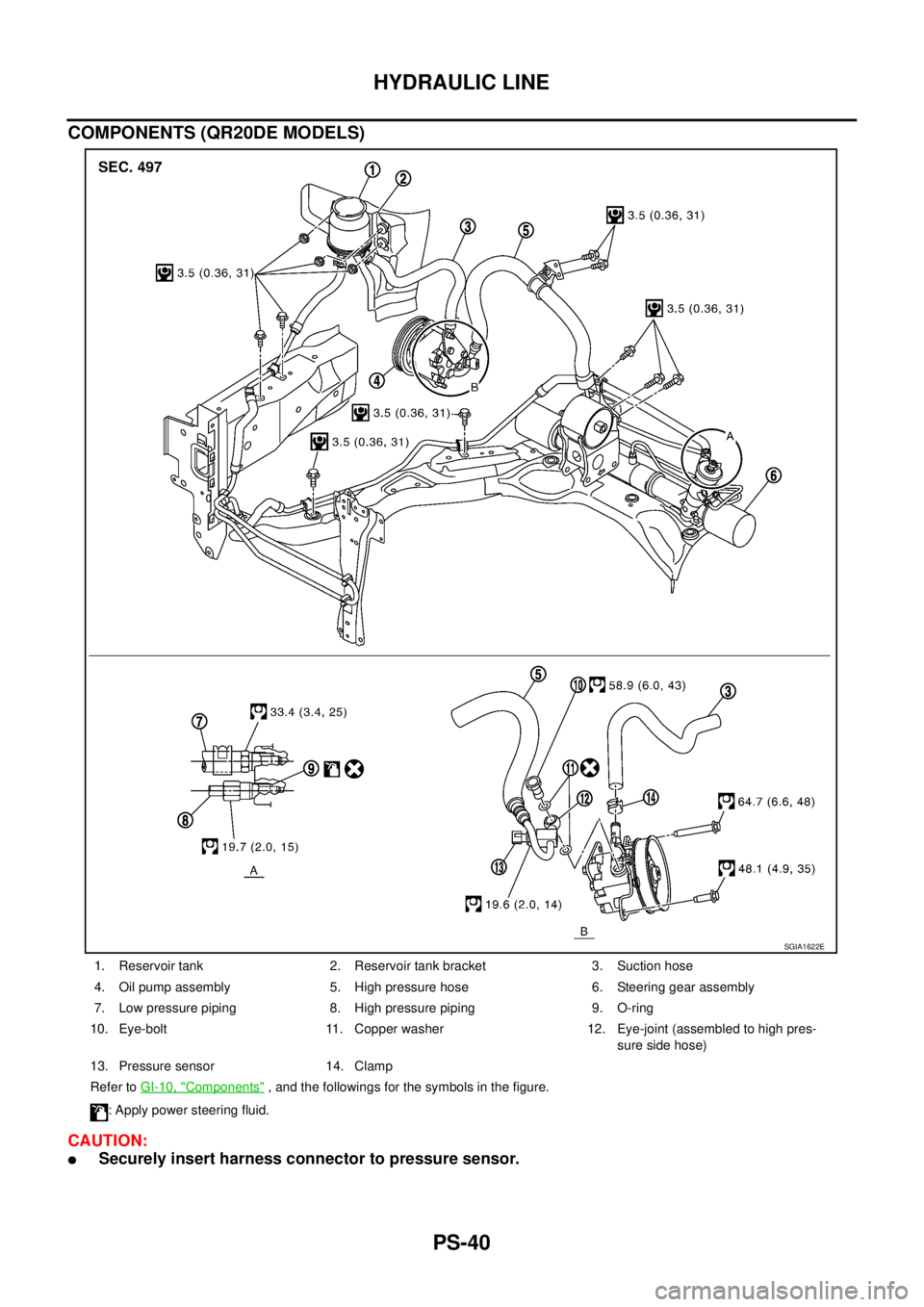
COMPONENTS (QR20DE MODELS)
CAUTION:
�Securely insert harness connector to pressure sensor.
1. Reservoir tank 2. Reservoir tank bracket 3. Suction hose
4. Oil pump assembly 5. High pressure hose 6. Steering gear assembly
7. Low pressure piping 8. High pressure piping 9. O-ring
10. Eye-bolt 11. Copper washer 12. Eye-joint (assembled to high pres-
sure side hose)
13. Pressure sensor 14. Clamp
Refer to GI-10, "
Components" , and the followings for the symbols in the figure.
: Apply power steering fluid.
SGIA1622E
Page 3156 of 3502
PS-42
SERVICE DATA AND SPECIFICATIONS (SDS)
SERVICE DATA AND SPECIFICATIONS (SDS)PFP:00030
Steering WheelBGS00043
Steering AngleBGS00044
Steering ColumnBGS00045
STEERING COLUMN LENGTH
TILT MECHANISM OPERATING RANGE
Steering wheel axial end play 0 mm (0 in)
Steering wheel play 0 – 35 mm (0 – 1.38 in)
Steering wheel turning force Less than 45 N (4.6 kg, 10 lb)
Tire size 205/65R16 215/55R17
Inner wheel
Degree minute (Decimal degree)Minimum 37°00′ (37.0°)33°00′ (33.0°)
Nominal 41°00′ (41.0°)37°00′ (37.0°)
Maximum 42°00′ (42.0°)38°00′ (38.0°)
Outer wheel
Degree minute (Decimal degree)Nominal 33°00′ (33.0°)31°00′ (31.0°)
Steering column length L 510.5 mm (20.10 in)
SGIA0986E
Tilt mechanism operating range L 31.5 mm (1.240 in)
SGIA1616E
Page 3157 of 3502

PS-43
C
D
E
F
H
I
J
K
L
MA
B
PS
Steering GearBGS00046
STEERING OUTER SOCKET AND INNER SOCKET
RACK STROKE
RACK SLIDING FORCE
Oil PumpBGS00048
Steering FluidBGS00")
SERVICE DATA AND SPECIFICATIONS (SDS)
PS-43
C
D
E
F
H
I
J
K
L
MA
B
PS
Steering GearBGS00046
STEERING OUTER SOCKET AND INNER SOCKET
RACK STROKE
RACK SLIDING FORCE
Oil PumpBGS00048
Steering FluidBGS00049
Steering gear typePR26AM
Outer socketSwinging torque 0.3 – 2.9 N·m (0.03 – 0.29 kg-m, 3 – 25 in-lb)
Measurement on spring balance
�Measuring point at cotter pin hole of stud4.84 – 46.7 N (0.5 – 4.8 kg, 1 – 10 lb)
Rotating torque 0.3 – 2.9 N·m (0.03 – 0.29 kg-m, 3 – 25 in-lb)
Axial end play 0.5 mm (0.020 in) or less
Inner socketSwinging torque 1.0 – 7.8 N·m (0.11 – 0.79 kg-m, 9 – 69 in-lb)
Measurement on spring balance
�Measuring point at *mark shown in the figure12.1 – 93.7 N (1.2 – 9.6 kg, 3 – 21 lb)
Axial end play 0.2 mm (0.008 in) or less
Inner socket length L127.3 mm (5.01 in)
SGIA0950E
Steering gear typePR26AM
Tire size 205/65R16 215/55R17
Rack stroke neutral position, dimension L (rack stroke) 73.5 mm (2.894 in) 68.5 mm (2.697 in)
SGIA0629J
Rack sliding force 210.6 – 269.4 N (21.5 – 27.5 kg, 47 – 61 lb)
Oil pump relief hydraulic pressureExcept for QR20DE models8,000 – 8,800 kPa
(80 – 88 bar, 81.6 – 89.8 kg/cm
2 , 1,160 – 1,276 psi)
QR20DE models9,000 – 9,800 kPa
(90 – 98 bar, 91.8 – 100 kg/cm
2 , 1,305 – 1,421 psi)
Fluid capacity
Approx. 1.0 (7/8 Imp qt)


1. Reservoir tank 2. Reservoir tank bracket 3. Suction h")

SERVICE DATA AND SPECIFICATIONS (SDS)PFP:00030
Steering WheelBGS00043
Steering AngleBGS00044
Steering ColumnBGS00045
STEERING COLUMN LENGTH
TILT MECHANISM")