Page 974 of 3502
![NISSAN TEANA 2003 Service Manual CO-22
[QR]
WATER PUMP
WATE R P U M PPFP:21020
Removal and InstallationBBS005AA
REMOVAL
1. Drain engine coolant from radiator drain plug at the bottom of radiator and from water drain plug on engine](/manual-img/5/57392/w960_57392-973.png "NISSAN TEANA 2003 Service Manual CO-22
[QR]
WATER PUMP
WATE R P U M PPFP:21020
Removal and InstallationBBS005AA
REMOVAL
1. Drain engine coolant from radiator drain plug at the bottom of radiator and from water drain plug on engine")
CO-22
[QR]
WATER PUMP
WATE R P U M PPFP:21020
Removal and InstallationBBS005AA
REMOVAL
1. Drain engine coolant from radiator drain plug at the bottom of radiator and from water drain plug on engine
cylinder block. Refer to CO-10, "
Changing Engine Coolant" and EM-81, "CYLINDER BLOCK" .
CAUTION:
�Perform this step when engine is cold.
�Do not spill engine coolant on drive belt.
2. Remove the following parts.
�Undercover and splash guard (RH)
�Drive belt; Refer to EM-14, "DRIVE BELTS" .
�Drive belt auto-tensioner; Refer to EM-15, "Removal and Installation of Drive Belt Auto-Tensioner" .
3. Remove water pump.
�Engine coolant will leak from cylinder block, so have a receptacle ready below.
CAUTION:
�Handle water pump vane so that it does not contact any other parts.
�Water pump cannot be disassembled and should be replaced as a unit.
4. Remove water pump housing with the following procedure;
a. Remove alternator. Refer to SC-27, "
CHARGING SYSTEM" .
b. Remove oil level gauge and oil level gauge guide. Refer to EM-26, "
OIL PAN AND OIL STRAINER" .
CAUTION:
Plug the oil level gauge guide opening to prevent oil pan from entering foreign materials.
c. Remove mounting bolts for water pipe.
d. Remove water pump housing.
5. Remove exhaust manifold and three way catalyst assembly. Refer to EM-23, "
EXHAUST MANIFOLD
AND THREE WAY CATALYST" .
6. Remove water pipe.
PBIC2253E
1. Water pump 2. Gasket 3. Gasket
4. Water pump housing 5. Gasket 6. Water pipe
7. O-ring
Page 975 of 3502
WATER PUMP
CO-23
[QR]
C
D
E
F
G
H
I
J
K
L
MA
CO
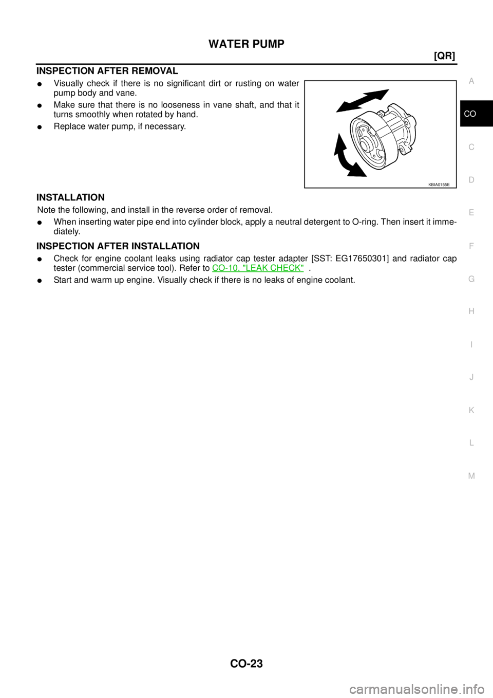
INSPECTION AFTER REMOVAL
�Visually check if there is no significant dirt or rusting on water
pump body and vane.
�Make sure that there is no looseness in vane shaft, and that it
turns smoothly when rotated by hand.
�Replace water pump, if necessary.
INSTALLATION
Note the following, and install in the reverse order of removal.
�When inserting water pipe end into cylinder block, apply a neutral detergent to O-ring. Then insert it imme-
diately.
INSPECTION AFTER INSTALLATION
�Check for engine coolant leaks using radiator cap tester adapter [SST: EG17650301] and radiator cap
tester (commercial service tool). Refer to CO-10, "
LEAK CHECK" .
�Start and warm up engine. Visually check if there is no leaks of engine coolant.
KBIA0155E
Page 976 of 3502
![NISSAN TEANA 2003 Service Manual CO-24
[QR]
THERMOSTAT AND WATER CONTROL VALVE
THERMOSTAT AND WATER CONTROL VALVEPFP:21200
Removal and InstallationBBS005AB
REMOVAL
1. Drain engine coolant from radiator drain plug at the bottom of r](/manual-img/5/57392/w960_57392-975.png "NISSAN TEANA 2003 Service Manual CO-24
[QR]
THERMOSTAT AND WATER CONTROL VALVE
THERMOSTAT AND WATER CONTROL VALVEPFP:21200
Removal and InstallationBBS005AB
REMOVAL
1. Drain engine coolant from radiator drain plug at the bottom of r")
CO-24
[QR]
THERMOSTAT AND WATER CONTROL VALVE
THERMOSTAT AND WATER CONTROL VALVEPFP:21200
Removal and InstallationBBS005AB
REMOVAL
1. Drain engine coolant from radiator drain plug at the bottom of radiator and from water drain plug on engine
cylinder block. Refer to CO-10, "
Changing Engine Coolant" and EM-81, "CYLINDER BLOCK" .
CAUTION:
�Perform this step when engine is cold.
�Do not spill engine coolant on drive belt.
2. Disconnect radiator hose (lower) at water inlet side. Refer to CO-13, "
RADIATOR" .
3. Remove water inlet and thermostat.
4. Remove water control valve with the following procedure:
a. Disconnect radiator hose (upper) at water control valve housing (water outlet) side.
b. Disconnect harness connector from engine coolant temperature sensor.
c. Remove heater pipe and heater hose.
d. After removing water control valve housing (water outlet), remove water control valve.
1. Thermostat 2. O-ring 3. Water inlet
4. Water control valve 5. O-ring 6. Gasket
7. Water control valve housing (water outlet) 8. Washer 9. Engine coolant temperature sensor
10. Heater hose 11. O-ring 12. Heater pipe
13. Heater hose
PBIC3519E
Page 977 of 3502
![NISSAN TEANA 2003 Service Manual THERMOSTAT AND WATER CONTROL VALVE
CO-25
[QR]
C
D
E
F
G
H
I
J
K
L
MA
CO
INSPECTION AFTER REMOVAL
�Place a string so that it is caught in the valves of thermostat and
water control valve. Immerse ful](/manual-img/5/57392/w960_57392-976.png "NISSAN TEANA 2003 Service Manual THERMOSTAT AND WATER CONTROL VALVE
CO-25
[QR]
C
D
E
F
G
H
I
J
K
L
MA
CO
INSPECTION AFTER REMOVAL
�Place a string so that it is caught in the valves of thermostat and
water control valve. Immerse ful")
THERMOSTAT AND WATER CONTROL VALVE
CO-25
[QR]
C
D
E
F
G
H
I
J
K
L
MA
CO
INSPECTION AFTER REMOVAL
�Place a string so that it is caught in the valves of thermostat and
water control valve. Immerse fully in a container filled with water.
Heat while stirring. (The example in the figure shows thermo-
stat.)
�The valve opening temperature is the temperature at which the
valve opens and falls from the thread.
�Continue heating. Check the maximum valve lift amount.
NOTE:
The maximum valve lift amount standard temperature for water
control valve is the reference value.
�After checking the maximum valve lift amount, lower the water
temperature and check the valve closing temperature.
Standard:
�If out of the standard, replace either or both thermostat and water control valve.
INSTALLATION
Note the following, and install in the reverse order of removal.
Thermostat and Water Control Valve
�Install thermostat with making rubber ring groove fit to thermo-
stat flange with the whole circumference. (The example in the
figure shows thermostat.)
NOTE:
Same procedure is applied for installation of water control valve.
�Install thermostat with jiggle valve facing upwards. (The position
deviation may be within the range of 20 degrees as shown in the
figure.)
�Install water control valve with the arrow facing up and the frame
center part facing upwards. (The position deviation may be
within the range of 20 degrees as shown in the figure.)
Heater Pipe Installation
Apply a neutral detergent to O-ring, then quickly insert the insertion part of heater pipe into cylinder block.
INSPECTION AFTER INSTALLATION
�Check for leaks of engine coolant using radiator cap tester adapter [SST: EG17650301] and a radiator cap
tester (commercial service tool). Refer to CO-10, "
LEAK CHECK" .
�Start and warm up engine. Visually check if there is no leaks of engine coolant and A/T fluid.
SLC252B
Items Thermostat Water control valve
Valve opening temperature 80.5 - 83.5°C (177 - 182°F) 93.5 - 96.5°C (200 - 206°F)
Maximum valve lift 8 mm/ 95°C (0.315 in/ 203°F) 8 mm/ 108°C (0.315 in/ 226°F)
Valve closing temperature 77°C (171°F) 90°C (194°F)
PBIC0157E
PBIC0158E
Page 978 of 3502
CO-26
[QR]
SERVICE DATA AND SPECIFICATIONS (SDS)
SERVICE DATA AND SPECIFICATIONS (SDS)PFP:00030
Standard and LimitBBS005AC
ENGINE COOLANT CAPACITY (APPROXIMATE)
Unit: (lmp qt)
THERMOSTAT
WATER CONTROL VALVE
*: Reference data
RADIATOR
Unit: kPa (bar, kg/cm2 , psi)
Engine coolant capacity (With reservoir tank at “MAX” level) 7.4 (6-1/2)
Reservoir tank engine coolant capacity (At “MAX” level) 0.8 (3/4)
Valve opening temperature 80.5 - 83.5°C (177 - 182°F)
Maximum valve lift 8 mm/ 95°C (0.315 in/ 203°F)
Valve closing temperature 77°C (171°F)
Valve opening temperature 93.5 - 96.5°C (200 - 206°F)
Maximum valve lift 8 mm/ 108°C (0.315 in/ 226°F)*
Valve closing temperature 90°C (194°F)
Cap relief pressureStandard 78 - 98 (0.78 - 0.98, 0.8 - 1.0, 11- 14)
Limit 59 (0.59, 0.6, 9)
Leakage test pressure 157 (1.57, 1.6, 23)
Page 980 of 3502
CO-28
[VQ]
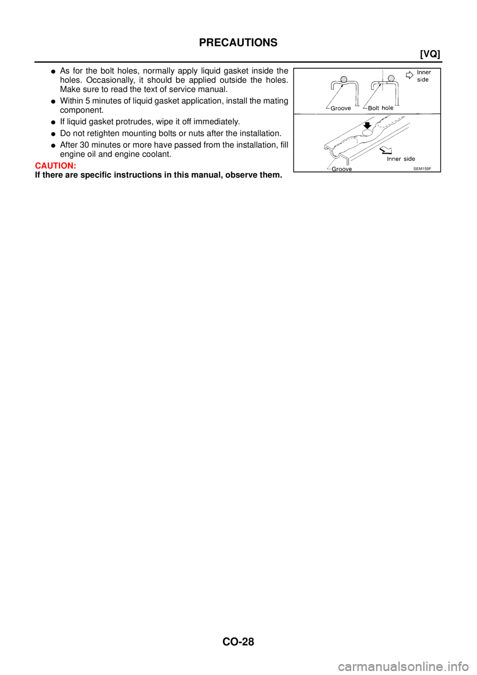
PRECAUTIONS
�As for the bolt holes, normally apply liquid gasket inside the
holes. Occasionally, it should be applied outside the holes.
Make sure to read the text of service manual.
�Within 5 minutes of liquid gasket application, install the mating
component.
�If liquid gasket protrudes, wipe it off immediately.
�Do not retighten mounting bolts or nuts after the installation.
�After 30 minutes or more have passed from the installation, fill
engine oil and engine coolant.
CAUTION:
If there are specific instructions in this manual, observe them.
SEM159F
Page 982 of 3502
![NISSAN TEANA 2003 Service Manual CO-30
[VQ]
OVERHEATING CAUSE ANALYSIS
OVERHEATING CAUSE ANALYSISPFP:00012
Troubleshooting ChartBBS004WV
Symptom Check items
Cooling sys-
tem parts
malfunctionPoor heat transferWater pump malfunctio](/manual-img/5/57392/w960_57392-981.png "NISSAN TEANA 2003 Service Manual CO-30
[VQ]
OVERHEATING CAUSE ANALYSIS
OVERHEATING CAUSE ANALYSISPFP:00012
Troubleshooting ChartBBS004WV
Symptom Check items
Cooling sys-
tem parts
malfunctionPoor heat transferWater pump malfunctio")
CO-30
[VQ]
OVERHEATING CAUSE ANALYSIS
OVERHEATING CAUSE ANALYSISPFP:00012
Troubleshooting ChartBBS004WV
Symptom Check items
Cooling sys-
tem parts
malfunctionPoor heat transferWater pump malfunction Worn or loose drive belt
— Thermostat stuck closed —
Damaged finsDust contamination or
paper clogging
Physical damage
Clogged radiator cooling
tubeExcess foreign material
(rust, dirt, sand, etc.)
Reduced air flowCooling fan does not oper-
ate
Fan assembly — High resistance to fan rota-
tion
Damaged fan blades
Damaged radiator shroud — — —
Improper engine coolant
mixture ratio—— —
Poor engine coolant quality — Engine coolant viscosity —
Insufficient engine coolantEngine coolant leaksCooling hoseLoose clamp
Cracked hose
Water pump Poor sealing
Radiator capLoose
Poor sealing
RadiatorO-ring for damage, deterio-
ration or improper fitting
Cracked radiator tank
Cracked radiator core
Reservoir tank Cracked reservoir tank
Overflowing reservoir tankExhaust gas leaks into
cooling systemCylinder head deterioration
Cylinder head gasket dete-
rioration
Page 986 of 3502
![NISSAN TEANA 2003 Service Manual CO-34
[VQ]
ENGINE COOLANT
ENGINE COOLANTPFP:KQ100
InspectionBBS004WY
LEVEL CHECK
�Check if the reservoir tank engine coolant level is within the
“MIN” to “MAX” range when engine is cool.
�Ad](/manual-img/5/57392/w960_57392-985.png "NISSAN TEANA 2003 Service Manual CO-34
[VQ]
ENGINE COOLANT
ENGINE COOLANTPFP:KQ100
InspectionBBS004WY
LEVEL CHECK
�Check if the reservoir tank engine coolant level is within the
“MIN” to “MAX” range when engine is cool.
�Ad")
CO-34
[VQ]
ENGINE COOLANT
ENGINE COOLANTPFP:KQ100
InspectionBBS004WY
LEVEL CHECK
�Check if the reservoir tank engine coolant level is within the
“MIN” to “MAX” range when engine is cool.
�Adjust the engine coolant level as necessary.
LEAK CHECK
�To check for leaks, apply pressure to the cooling system with
radiator cap tester (commercial service tool) and radiator cap
tester adapter (SST).
WARNING:
Do not remove radiator cap when engine is hot. Serious
burns could occur from high-pressure engine coolant
escaping from radiator.
CAUTION:
Higher testing pressure than specified may cause radiator
damage.
NOTE:
In a case engine coolant decreases, replenish radiator with engine coolant.
�If anything is found, repair or replace damaged parts.
Changing Engine CoolantBBS004WZ
WARNING:
�To avoid being scalded, do not change engine coolant when engine is hot.
�Wrap a thick cloth around radiator cap and carefully remove the cap. First, turn the cap a quarter
of a turn to release built-up pressure. Then turn the cap all the way.
�Be careful not to allow engine coolant to contact drive belts.
DRAINING ENGINE COOLANT
1. Remove grommet from undercover.
2. Open radiator drain plug at the bottom of radiator, and then remove radiator cap.
When drain all of engine coolant in the system, open water drain plugs on cylinder block. Refer to
EM-229, "
DISASSEMBLY" .
3. Remove reservoir tank as necessary, and drain engine coolant and clean reservoir tank before installing.
SMA412B
Testing pressure
: 157 kPa (1.57 bar, 1.6 kg/cm
2 , 23 psi)
SLC756AA
PBIC2512E
![NISSAN TEANA 2003 Service Manual CO-26
[QR]
SERVICE DATA AND SPECIFICATIONS (SDS)
SERVICE DATA AND SPECIFICATIONS (SDS)PFP:00030
Standard and LimitBBS005AC
ENGINE COOLANT CAPACITY (APPROXIMATE)
Unit: (lmp qt)
THERMOSTAT
WATER CO](/manual-img/5/57392/w960_57392-977.png "NISSAN TEANA 2003 Service Manual CO-26
[QR]
SERVICE DATA AND SPECIFICATIONS (SDS)
SERVICE DATA AND SPECIFICATIONS (SDS)PFP:00030
Standard and LimitBBS005AC
ENGINE COOLANT CAPACITY (APPROXIMATE)
Unit: (lmp qt)
THERMOSTAT
WATER CO")