Page 346 of 3502

AT-338
REPAIR FOR COMPONENT PARTS
b. Move side gear up and down to measure dial indicator deflec-
tion. Always measure indicator deflection on both side gears.
c. If not within specification, adjust clearance by changing thick-
ness of differential side gear thrust washers. Refer to “Parts
Information” for side gear thrust washers selection.
4. Install lock pin with pin punch.
CAUTION:
�Do not reuse lock pin.
�Make sure that lock pin is flush with differential case.
5. Press on differential side bearings.
CAUTION:
Apply ATF to differential side bearings.
6. Install differential side bearing outer race and differential side
bearing adjusting shim on transaxle case. Refer to AT- 3 4 0 ,
"Adjustment (1)" .
7. Tighten final gear and tighten fixing bolts to the specified torque
in numerical order as shown in the figure after temporarily tight-
ening them. Refer to AT- 3 3 5 , "
COMPONENTS" . Clearance between side gear and differential
case with washer:
Refer to AT- 3 6 7 , "
Final Drive" .
SMT611A
SAT904DA
SAT545FA
ATM0432D
Page 347 of 3502
ASSEMBLY
AT-339
D
E
F
G
H
I
J
K
L
MA
B
AT
ASSEMBLYPFP:00000
Assembly (1)BCS001OW
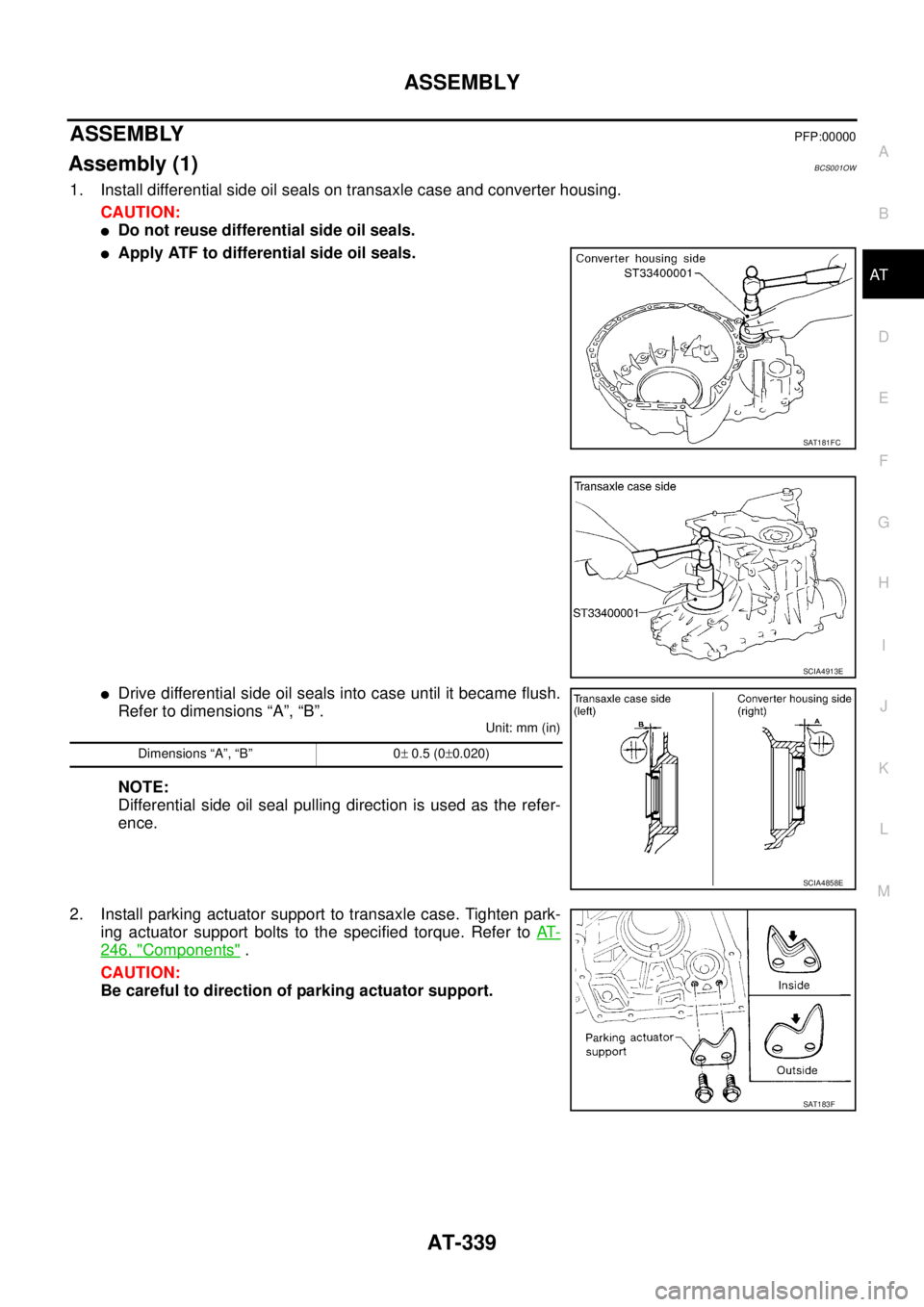
1. Install differential side oil seals on transaxle case and converter housing.
CAUTION:
�Do not reuse differential side oil seals.
�Apply ATF to differential side oil seals.
�Drive differential side oil seals into case until it became flush.
Refer to dimensions “A”, “B”.
Unit: mm (in)
NOTE:
Differential side oil seal pulling direction is used as the refer-
ence.
2. Install parking actuator support to transaxle case. Tighten park-
ing actuator support bolts to the specified torque. Refer to AT-
246, "Components" .
CAUTION:
Be careful to direction of parking actuator support.
SAT181FC
SCIA4913E
Dimensions “A”, “B” 0± 0.5 (0±0.020)
SCIA4858E
SAT183F
Page 348 of 3502
AT-340
ASSEMBLY
3. Install parking pawl on transaxle case and fix it with parking
shaft.
4. Install return spring and parking pawl spacer.
Adjustment (1)BCS001OX
DIFFERENTIAL SIDE BEARING PRELOAD
1. Install differential side bearing outer race without differential side
bearing adjusting shim on transaxle case.
CAUTION:
Apply ATF to differential side bearing outer race.
2. Install differential side bearing outer race on converter housing.
CAUTION:
Apply ATF to differential side bearing outer race.
3. Place final drive assembly on transaxle case.
4. Install converter housing on transaxle case. Tighten converter
housing mounting bolts to the specified torque. Refer to AT- 2 4 6 ,
"Components" .
SCIA4881E
SAT870D
SAT008F
Page 349 of 3502

ASSEMBLY
AT-341
D
E
F
G
H
I
J
K
L
MA
B
AT
5. Attach dial indicator on differential case at converter housing
side.
6. Insert SST into differential side gear from transaxle case side.
7. Move SST up and down and measure dial indicator deflection.
8. Select proper thickness of differential side bearing adjusting
shim. Refer to “Parts Information” for differential side bearing
adjusting shim selection.
Suitable shim thickness = Dial indicator deflection + Speci-
fied bearing preload
9. Remove converter housing from transaxle case.
10. Remove final drive assembly from transaxle case.
11. Remove differential side bearing outer race from transaxle case.
12. Reinstall differential side bearing outer race and differential side
bearing adjusting shim selected from “Parts Information” on
transaxle case.
13. Reinstall converter housing on transaxle case and tighten con-
verter housing mounting bolts to the specified torque. Refer to
AT- 2 4 6 , "
Components" .
14. Insert SST and measure turning torque of final drive assembly.
�Turn final drive assembly in both directions several times
to seat bearing rollers correctly.
�When old bearing is used again, turning torque will be
slightly less than the above.
�Make sure torque is close to the specified range.
REDUCTION PINION GEAR BEARING PRELOAD
1. Remove converter housing and final drive assembly from tran-
saxle case.
2. Select proper thickness of reduction pinion gear bearing adjust-
ing shim using the following procedures.
a. Place reduction pinion gear on transaxle case as shown.Suitable shim thickness = Dial indicator deflection +
Specified bearing preload
Bearing preload: Refer to AT- 3 6 7 , "
Final Drive" .
SAT186FA
SAT010FC
Turning torque of final drive assembly
(New bearing):
Refer to AT- 3 6 7 , "
Final Drive" .
SCIA4914E
SCIA3623E
Page 365 of 3502
ASSEMBLY
AT-357
D
E
F
G
H
I
J
K
L
MA
B
AT
10. Install final drive assembly on transaxle case.
11. Install differential lubricant tube (1) and clips (2) on converter
housing. Tighten differential lubricant tube bolts to the specified
torque. Refer to AT- 2 4 6 , "
Components" .
12. Install O-ring on differential oil port of transaxle case.
13. Apply locking sealant (Loctite # 518) to transaxle case as shown
in figure.
CAUTION:
Completely remove all moisture, oil and old sealant, etc.
from the transaxle case and converter housing mounting
surfaces.
14. Install converter housing on transaxle case. Tighten converter
housing mounting bolts to the specified torque. Refer to AT- 2 4 6 ,
"Components" .
15. Install O-ring on plug.
CAUTION:
Do not reuse O-ring.
16. Install plug on converter housing.
SAT228F
SCIA7817E
SCIA3281E
SCIA4929E
SAT008F
Page 375 of 3502

AT-367
D
E
F
G
H
I
J
K
L
MA
B
AT
CLUTCH AND BRAKE RETURN SPRINGS
Unit: mm (in)
BRAKE BAND
Final DriveBCS001P5
DIFFERENTIAL SIDE GEAR CLEARANCE
BEARING PRELOAD
T")
SERVICE DATA AND SPECIFICATIONS (SDS)
AT-367
D
E
F
G
H
I
J
K
L
MA
B
AT
CLUTCH AND BRAKE RETURN SPRINGS
Unit: mm (in)
BRAKE BAND
Final DriveBCS001P5
DIFFERENTIAL SIDE GEAR CLEARANCE
BEARING PRELOAD
TURNING TORQUE
Planetary Carrier and Oil PumpBCS001P6
PLANETARY CARRIER
OIL PUMP
Input ShaftBCS001P7
SEAL RING CLEARANCE
SEAL RING
Reduction Pinion GearBCS001P8
TURNING TORQUE
Parts Free length Outer diameter
Forward clutch (Overrun clutch)
(22 pcs)21.4 (0.843) 10.3 (0.406)
High clutch (10 pcs) 20.8 (0.819) 10.8 (0.425)
Low & reverse brake (24 pcs) 24.1 (0.949) 6.6 (0.260)
Anchor end pin tightening torque N-m (kg-m, in-lb) 4.9 (0.50, 43)
Number of returning revolutions for anchor end pin 2.5
Lock nut tightening torque N-m (kg-m, ft-lb) 34 (3.5, 25)
Clearance between side gear and differential case with
washer mm (in)0.1 - 0.2 (0.004 - 0.008)
Differential side bearing preload mm (in) 0.05 - 0.09 (0.0020 - 0.0035)
Turning torque of final drive assembly N-m (kg-cm, in-lb) 0.8 - 1.5 (8.0 - 15.7, 7 - 13)
Clearance between planetary carrier
and pinion washer mm (in)Standard 0.20 - 0.70 (0.0079 - 0.0276)
Allowable limit 0.80 (0.0315)
Oil pump side clearance mm (in) 0.030 - 0.050 (0.0012 - 0.0020)
Clearance between oil pump
housing and outer gear mm
(in)Standard 0.111 - 0.181 (0.0044 - 0.0071)
Allowable limit 0.181 (0.0071)
Oil pump cover seal ring
clearance mm (in)Standard 0.1 - 0.35 (0.0039 - 0.0138)
Allowable limit 0.35 (0.0138)
Input shaft seal ring clearance mm (in)Standard 0.08 - 0.23 (0.0031 - 0.0091)
Allowable limit 0.23 (0.0091)
Outer diameter mm (in) Inner diameter mm (in) Width mm (in)
26 (1.024) 22.6 (0.890) 1.97 (0.078)
Turning torque of reduction pinion gear N-m (kg-cm, in-lb) 0.05 - 0.39 (0.5 - 4.0, 0.43 - 3.47)
Page 1011 of 3502

CVT-5
D
E
F
G
H
I
J
K
L
MA
B
CVT
TABLE ............................................................... 183
Component Inspection ......................................... 184
SHIFT LOCK SOLENOID ................................. 184
DETENTION SWITCH (FOR KEY) ................... 184
DETENTION SWITCH (FOR SHIFT) ................ 184
KEY LOCK SOLENOID ..................................... 184
IGNITION KNOB SWITCH ................................ 185
STOP LAMP SWITCH ...................................... 185
AIR BREATHER HOSE .......................................... 186
Removal and Installation ...................................... 186
COMPONENTS ................................................ 186
REMOVAL ......................................................... 186
INSTALLATION ................................................. 186
DIFFERENTIAL SIDE OIL SEAL ........................... 187
Removal and Installation ...................................... 187
COMPONENTS ................................................ 187
REMOVAL ......................................................... 187
INSTALLATION ................................................. 188CVT FLUID COOLER SYSTEM ..............................189
CVT Fluid Cooler Removal and Installation ..........189
COMPONENTS .................................................189
REMOVAL .........................................................190
INSTALLATION .................................................192
COMPONENT INSPECTION ............................192
TRANSAXLE ASSEMBLY ......................................193
Removal and Installation ......................................193
COMPONENTS .................................................193
REMOVAL .........................................................194
INSPECTION ....................................................196
INSTALLATION .................................................196
SERVICE DATA AND SPECIFICATIONS (SDS) ....198
General Specifications ..........................................198
Vehicle Speed at Which Gear Shifting Occurs .....198
Stall Speed ...........................................................198
Line Pressure .......................................................198
Solenoid Valves ....................................................198
CVT Fluid Temperature Sensor ............................199
Primary Speed Sensor .........................................199
Secondary Speed Sensor .....................................199
Removal and Installation ......................................199
Page 1018 of 3502
CVT-12
PREPARATION
PREPARATIONPFP:00002
Special Service ToolsBCS001FV
Commercial Service ToolsBCS001FW
Tool number
Tool nameDescription
ST2505S001
Oil pressure gauge set
1. ST25051001
Oil pressure gauge
2. ST25052000
Hose
3. ST25053000
Joint pipe
4. ST25054000
Adapter
5. ST25055000
AdapterMeasuring line pressure
ST33400001
Drift
a: 60 mm (2.36 in) dia.
b: 47 mm (1.85 in) dia. Installing differential side oil seal
SCIA3695J
NT086
Tool number
Tool nameDescription
31197CA000
Drive plate location guide
a: 14 mm (0.55 in) dia.Installing transaxle assembly
31093CA000
SlingerRemoving and installing transaxle assembly
31092CA000
SlingerRemoving and installing transaxle assembly
Power toolLoosening nuts and bolts
SCIA2013E
SCIA2014E
SCIA2015E
PBIC0190E
BCS001OX
DIFFERENTIAL SIDE BEARING PRELOAD
1.")
 and clips (2) on converter
housing. Tighten differential lub")
