Page 869 of 3502
TROUBLE DIAGNOSIS
BRC-9
[ABS]
C
D
E
G
H
I
J
K
L
MA
B
BRC
DIAGNOSIS FLOW CHART
SFIA3270E
Page 870 of 3502
BRC-10
[ABS]
TROUBLE DIAGNOSIS
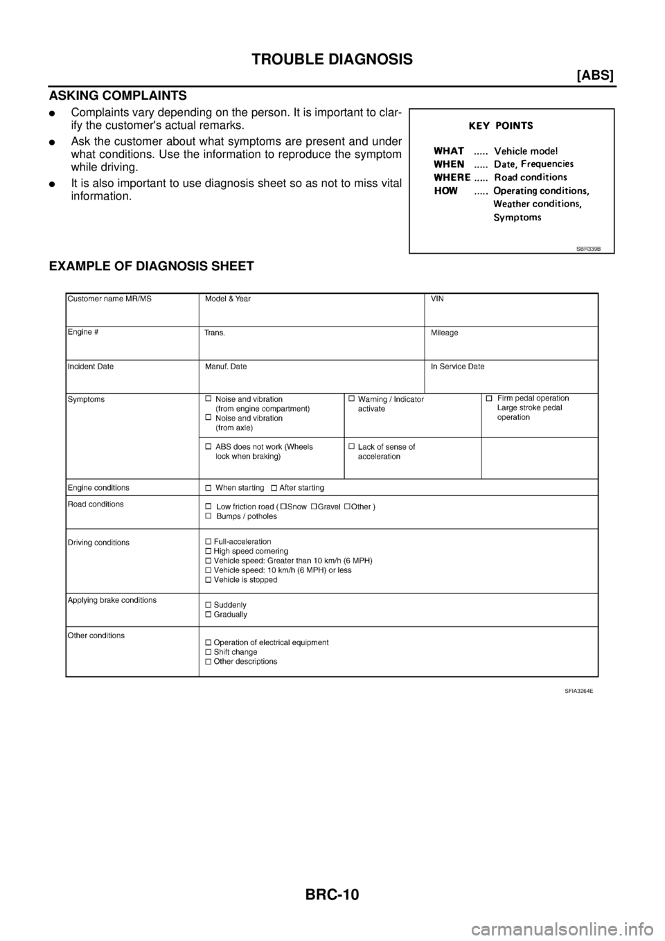
ASKING COMPLAINTS
�Complaints vary depending on the person. It is important to clar-
ify the customer's actual remarks.
�Ask the customer about what symptoms are present and under
what conditions. Use the information to reproduce the symptom
while driving.
�It is also important to use diagnosis sheet so as not to miss vital
information.
EXAMPLE OF DIAGNOSIS SHEET
SBR339B
SFIA3264E
Page 871 of 3502
TROUBLE DIAGNOSIS
BRC-11
[ABS]
C
D
E
G
H
I
J
K
L
MA
B
BRC
Component Parts LocationBFS000CV
SFIA2518E
Page 872 of 3502
BRC-12
[ABS]
TROUBLE DIAGNOSIS
SchematicBFS000CW
TFWM0246E
Page 873 of 3502
TROUBLE DIAGNOSIS
BRC-13
[ABS]
C
D
E
G
H
I
J
K
L
MA
B
BRC
Wiring Diagram — ABS —BFS000CX
TFWM0247E
Page 874 of 3502
BRC-14
[ABS]
TROUBLE DIAGNOSIS
TFWM0248E
Page 875 of 3502
TROUBLE DIAGNOSIS
BRC-15
[ABS]
C
D
E
G
H
I
J
K
L
MA
B
BRC
TFWM0249E
Page 876 of 3502
![NISSAN TEANA 2003 Service Manual BRC-16
[ABS]
TROUBLE DIAGNOSIS
Control Unit Input/Output Signal SpecificationsBFS000CY
REFERENCE VALUE FROM CONSULT-II
CAUTION:
The monitor displays the control unit calculation data. The normal va](/manual-img/5/57392/w960_57392-875.png "NISSAN TEANA 2003 Service Manual BRC-16
[ABS]
TROUBLE DIAGNOSIS
Control Unit Input/Output Signal SpecificationsBFS000CY
REFERENCE VALUE FROM CONSULT-II
CAUTION:
The monitor displays the control unit calculation data. The normal va")
BRC-16
[ABS]
TROUBLE DIAGNOSIS
Control Unit Input/Output Signal SpecificationsBFS000CY
REFERENCE VALUE FROM CONSULT-II
CAUTION:
The monitor displays the control unit calculation data. The normal values will be displayed even that in
the event the output circuit (harness) is open or shorted.
Note 1: Confirm tire pressure is the standard value.
Note 2: Brake warning lamp can be used for EBD warning lamp.
Note 3: ON/OFF timing of ABS warning lamp
ON: For a while after ignition switch is turned ON, or when a malfunction is detected.
OFF: In a while after the warning lamp is ON (when the system is in normal operation). Monitor item Display itemDATA MONITOR
ConditionReference values for
normal operation
WHEEL SENSORVehicle speed calculated using sig-
nals from all four wheel sensorsVehicle stopped 0 [km/h (MPH)]
Vehicle running (Note 1)Almost in accordance
with speedometer dis-
play (within ± 10 %)
IN ABS S/V
OUT ABS S/VOperation condition of all solenoid
valvesWhen actuator (solenoid) operates or
during fail-safeON
When actuator relay operates and the
actuator (solenoid) does not operateOFF
EBD WARN LAMP
(Note 2)Brake warning lamp ON/OFF condi-
tionWhen brake warning lamp is ON ON
When brake warning lamp is OFF OFF
STOP LAMP SW Brake pedal operation conditionBrake pedal depressed ON
Brake pedal not depressed OFF
MOTOR RELAYMotor and motor relay operation con-
ditionWhen motor relay and motor are
operatingON
When motor relay and motor are not
operatingOFF
ACTUATOR RLY Actuator relay operation conditionActuator relay activated ON
Actuator relay not activated OFF
ABS WARN LAMPABS warning lamp ON/OFF condition
(Note 3)When ABS warning lamp is ON ON
When ABS warning lamp is OFF OFF
BATTERY VOLTBattery voltage supplied to ABS actu-
ator and electric unit (control unit)Ignition switch ON 10−16 V
EBD SIGNAL EBD operation signalEBD activated ON
EBD not activated OFF
ABS SIGNAL ABS operation signalABS activated ON
ABS not activated OFF
ABS FAIL SIG
Fail-safe signal conditionIn ABS fail-safe
OFF
EBD FAIL SIG In EBD fail-safe
![NISSAN TEANA 2003 Service Manual TROUBLE DIAGNOSIS
BRC-9
[ABS]
C
D
E
G
H
I
J
K
L
MA
B
BRC
DIAGNOSIS FLOW CHART
SFIA3270E](/manual-img/5/57392/w960_57392-868.png "NISSAN TEANA 2003 Service Manual TROUBLE DIAGNOSIS
BRC-9
[ABS]
C
D
E
G
H
I
J
K
L
MA
B
BRC
DIAGNOSIS FLOW CHART
SFIA3270E")
![NISSAN TEANA 2003 Service Manual TROUBLE DIAGNOSIS
BRC-11
[ABS]
C
D
E
G
H
I
J
K
L
MA
B
BRC
Component Parts LocationBFS000CV
SFIA2518E](/manual-img/5/57392/w960_57392-870.png "NISSAN TEANA 2003 Service Manual TROUBLE DIAGNOSIS
BRC-11
[ABS]
C
D
E
G
H
I
J
K
L
MA
B
BRC
Component Parts LocationBFS000CV
SFIA2518E")
![NISSAN TEANA 2003 Service Manual BRC-12
[ABS]
TROUBLE DIAGNOSIS
SchematicBFS000CW
TFWM0246E](/manual-img/5/57392/w960_57392-871.png "NISSAN TEANA 2003 Service Manual BRC-12
[ABS]
TROUBLE DIAGNOSIS
SchematicBFS000CW
TFWM0246E")
![NISSAN TEANA 2003 Service Manual TROUBLE DIAGNOSIS
BRC-13
[ABS]
C
D
E
G
H
I
J
K
L
MA
B
BRC
Wiring Diagram — ABS —BFS000CX
TFWM0247E](/manual-img/5/57392/w960_57392-872.png "NISSAN TEANA 2003 Service Manual TROUBLE DIAGNOSIS
BRC-13
[ABS]
C
D
E
G
H
I
J
K
L
MA
B
BRC
Wiring Diagram — ABS —BFS000CX
TFWM0247E")
![NISSAN TEANA 2003 Service Manual BRC-14
[ABS]
TROUBLE DIAGNOSIS
TFWM0248E](/manual-img/5/57392/w960_57392-873.png "NISSAN TEANA 2003 Service Manual BRC-14
[ABS]
TROUBLE DIAGNOSIS
TFWM0248E")
![NISSAN TEANA 2003 Service Manual TROUBLE DIAGNOSIS
BRC-15
[ABS]
C
D
E
G
H
I
J
K
L
MA
B
BRC
TFWM0249E](/manual-img/5/57392/w960_57392-874.png "NISSAN TEANA 2003 Service Manual TROUBLE DIAGNOSIS
BRC-15
[ABS]
C
D
E
G
H
I
J
K
L
MA
B
BRC
TFWM0249E")