Page 294 of 3502
AT-286
REPAIR FOR COMPONENT PARTS
d. Place control valve inter body as shown in figure (side of control
valve lower body face up). Install steel balls in their proper posi-
tions.
e. Install control valve inter body on control valve upper body using
reamer bolts f as guides.
CAUTION:
Be careful not to dislocate or drop steel balls.
f. Install check balls and oil cooler relief valve springs in their
proper positions in control valve lower body.
g. Install bolts e from bottom of control valve lower body. Using
bolts e as guides, install separating plate as a set.
h. Install support plates on control valve lower body.
i. Install control valve lower body on control valve inter body using
reamer bolts f as guides, and tighten reamer bolts f slightly.
SCIA3642E
SCIA4981E
SCIA4885E
SCIA7820E
SCIA7821E
Page 299 of 3502

REPAIR FOR COMPONENT PARTS
AT-291
D
E
F
G
H
I
J
K
L
MA
B
AT
c. Place mating surface of valve body face down, and remove
internal parts.
CAUTION:
�If a valve is hard to remove, place valve body face down
and lightly tap it with a soft hammer.
�Be careful not to drop or damage valves and sleeves.
INSPECTION
Valve Springs
�Measure free length and outer diameter of each valve spring.
Also check for damage or deformation. Refer to AT- 3 6 4 , "
Con-
trol Valves" .
�Replace valve springs if deformed or fatigued.
Control Valves
Check sliding surfaces of valves, sleeves and plugs. Replace if necessary.
ASSEMBLY
CAUTION:
�Apply ATF to all components before installation.
�Lay control valve body down when installing valves. Do not
stand control valve body upright.
�Lubricate control valve body and all valves with ATF. Install con-
trol valves by sliding them carefully into their bores.
CAUTION:
�Install each control valve one by one.
�Install control valves after checking, because some of
them are similar.
�Be careful not to scratch or damage valve body.
SAT137D
SAT138D
SAT139D
SAT140DA
Page 307 of 3502
REPAIR FOR COMPONENT PARTS
AT-299
D
E
F
G
H
I
J
K
L
MA
B
AT
5. Install drive plates, driven plates, retaining plate and dish plates.
Refer to AT- 3 6 6 , "
REVERSE CLUTCH" .
CAUTION:
Be careful to order of plates.
NOTE:
Install two dish plates fitting each installation direction with
reverse clutch drum groove displaced slightly.
6. Install snap ring with a flat-bladed screwdriver.
SCIA4888E
SAT254E
SCIA4886E
Page 320 of 3502
AT-312
REPAIR FOR COMPONENT PARTS
6. Install drive plates, driven plates, retaining plate and dish plates
for overrun clutch. Refer to AT- 3 6 6 , "
OVERRUN CLUTCH" .
CAUTION:
Be careful to the order of plates.
NOTE:
Install two dish plates fitting each installation direction with
groove displaced slightly.
7. Install snap ring for overrun clutch with flat-bladed screwdriver.
SCIA3036E
SAT254E
SCIA4895E
Page 325 of 3502
REPAIR FOR COMPONENT PARTS
AT-317
D
E
F
G
H
I
J
K
L
MA
B
AT
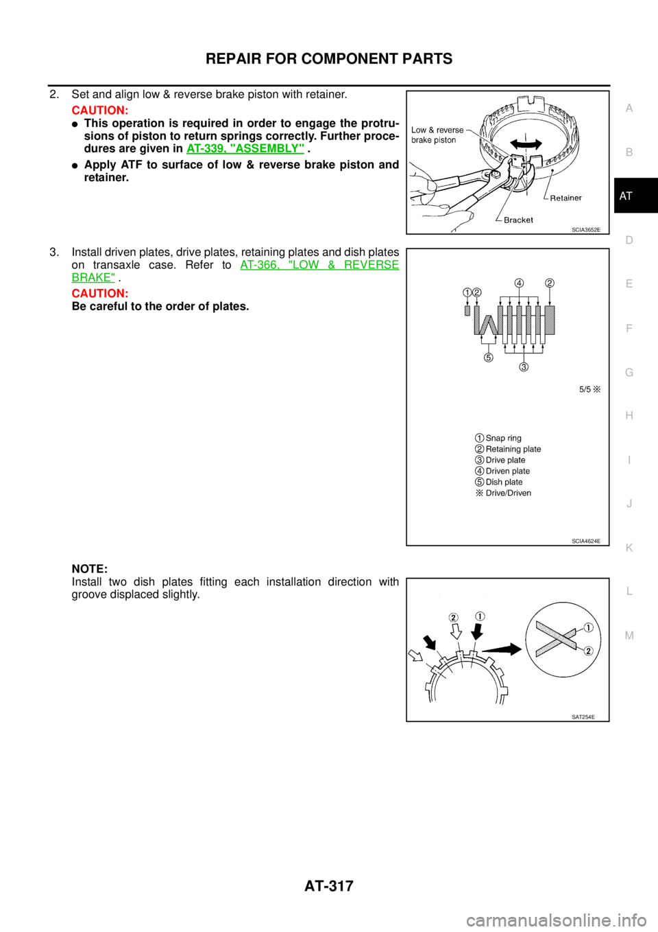
2. Set and align low & reverse brake piston with retainer.
CAUTION:
�This operation is required in order to engage the protru-
sions of piston to return springs correctly. Further proce-
dures are given in AT- 3 3 9 , "
ASSEMBLY" .
�Apply ATF to surface of low & reverse brake piston and
retainer.
3. Install driven plates, drive plates, retaining plates and dish plates
on transaxle case. Refer to AT- 3 6 6 , "
LOW & REVERSE
BRAKE" .
CAUTION:
Be careful to the order of plates.
NOTE:
Install two dish plates fitting each installation direction with
groove displaced slightly.
SCIA3652E
SCIA4624E
SAT254E
Page 349 of 3502

ASSEMBLY
AT-341
D
E
F
G
H
I
J
K
L
MA
B
AT
5. Attach dial indicator on differential case at converter housing
side.
6. Insert SST into differential side gear from transaxle case side.
7. Move SST up and down and measure dial indicator deflection.
8. Select proper thickness of differential side bearing adjusting
shim. Refer to “Parts Information” for differential side bearing
adjusting shim selection.
Suitable shim thickness = Dial indicator deflection + Speci-
fied bearing preload
9. Remove converter housing from transaxle case.
10. Remove final drive assembly from transaxle case.
11. Remove differential side bearing outer race from transaxle case.
12. Reinstall differential side bearing outer race and differential side
bearing adjusting shim selected from “Parts Information” on
transaxle case.
13. Reinstall converter housing on transaxle case and tighten con-
verter housing mounting bolts to the specified torque. Refer to
AT- 2 4 6 , "
Components" .
14. Insert SST and measure turning torque of final drive assembly.
�Turn final drive assembly in both directions several times
to seat bearing rollers correctly.
�When old bearing is used again, turning torque will be
slightly less than the above.
�Make sure torque is close to the specified range.
REDUCTION PINION GEAR BEARING PRELOAD
1. Remove converter housing and final drive assembly from tran-
saxle case.
2. Select proper thickness of reduction pinion gear bearing adjust-
ing shim using the following procedures.
a. Place reduction pinion gear on transaxle case as shown.Suitable shim thickness = Dial indicator deflection +
Specified bearing preload
Bearing preload: Refer to AT- 3 6 7 , "
Final Drive" .
SAT186FA
SAT010FC
Turning torque of final drive assembly
(New bearing):
Refer to AT- 3 6 7 , "
Final Drive" .
SCIA4914E
SCIA3623E
Page 353 of 3502

ASSEMBLY
AT-345
D
E
F
G
H
I
J
K
L
MA
B
AT
4. Measure dimensions “1 ” and “2 ” at side cover and then cal-
culate dimension “A”.
�Measure dimension “ 1” and “ 2” in at least two places.
5. Measure dimensions “
2 ” and “3 ” and then calculate dimen-
sion “B”.
�Measure dimension “ 2” and “ 3” in at least two places.
6. Select proper thickness of output shaft adjusting shim so that
output shaft end play (clearance between side cover and output
shaft bearing) is within specifications. Refer to “Parts Informa-
tion” for output shaft adjusting shim selection.
7. Install output shaft adjusting shim on output shaft bearing.
Assembly (2)BCS001OY
1. Apply locking sealant (Loctite # 518) to transaxle case as shown
in figure.
CAUTION:
Completely remove all moisture, oil and old sealant, etc.
from the transaxle case and side cover mounting surfaces.
2. Fit mounting part of output shaft bearing on side cover to output
shaft bearing, and after adjusting knock pin position, install it
with light taps of a soft hammer and things like that.
CAUTION:
When installing, to avoid getting damaged and deformed,
set mounting part straight to parallel with the mounting sur-
face.“A”: Distance between transaxle case fitting sur-
face and adjusting shim mating surface.
A =
1 − 2
2
: Height of gauge
SAT374F
“B”: Distance between the end of output shaft
bearing outer race and the side cover fitting
surface of transaxle case.
B =
2 − 3
2
: Height of gauge
SAT375F
Output shaft end play (A − B):
Refer to AT- 3 6 8 , "
Output Shaft" .
SCIA4918E
SCIA4919E
SAT442D
Page 394 of 3502
 Service Tools and EquipmentBJS000FD
Never mix HFC-134a (R-134a) refrigerant and/or its specified lubricant with CFC-12 (R-12) refrigerant and/or
its lubricant.
S")
ATC-16
PREPARATION
HFC-134a (R-134a) Service Tools and EquipmentBJS000FD
Never mix HFC-134a (R-134a) refrigerant and/or its specified lubricant with CFC-12 (R-12) refrigerant and/or
its lubricant.
Separate and non-interchangeable service equipment must be used for handling each type of refrigerant/lubri-
cant.
Refrigerant container fittings, service hose fittings and service equipment fittings (equipment which handles
refrigerant and/or lubricant) are different between CFC-12 (R-12) and HFC-134a (R-134a). This is to avoid
mixed use of the refrigerants/lubricant.
Never use adapters that convert one size fitting to another: refrigerant/lubricant contamination occurs and
compressor malfunction may result.
Tool number
Tool nameDescription
HFC-134a (R-134a) refrigerantContainer color: Light blue
Container marking: HFC-134a (R-
134a)
Fitting size: Thread size
�Large container 1/2″ -16 ACME
Nissan A/C System Oil Type S
(DH-PS)Type: Polyalkylene glycol oil (PAG),
type S (DH-PS)
Application: HFC-134a (R-134a) swash
plate compressors (Nissan only)
Capacity: 40 m (1.4 Imp fl oz.)
Recovery/Recycling/
Recharging equipment (ACR4)Function: Refrigerant recovery,
recycling and recharging
Electrical A/C leak detectorPower supply:
DC 12 V (Cigarette lighter)
S-NT196
S-NT197
RJIA0195E
SHA705EB
. Install steel balls in their proper posi-
tions.
e. Install control")