Page 613 of 3502

INTEGRATED COLOR DISPLAY SYSTEM
AV-85
C
D
E
F
G
H
I
J
L
MA
B
AV
On Board Self-Diagnosis FunctionBKS0027W
DESCRIPTION
�Trouble diagnosis function of system has a self-diagnosis mode by automatic operation and a confirma-
tion mode by manual operation.
�Self-diagnosis mode checks for connections between the units constituting this system, analyzes each
individual unit at the same time, and displays the results on the display.
�Confirmation mode displays trouble diagnosis that require an operation and a judgment by a human
(auto-decision cannot be performed by the system), and an error history of system.
DIAGNOSIS ITEM
Mode Description
DCU Failure Diagnosis
�Display control unit diagnosis
�Analyzes connection between the display control unit and each unit, and operation of
each unit.
DCU
ConfirmationDCUDisplay DiagnosisColor tone and shading of the display control unit-generated image can be checked by
the display of a color bar and a gray scale.
Vehicle SignalDiagnosis of signals that are input to display control unit can be performed for speed sig-
nal, Light, IGN and Reverse.
History of ErrorMalfunctions that occurred in the past are displayed, along with the number of times each
has occurred.
Software Version Software version of each unit is displayed.
HVAC Self-diagnosis of air conditioner system is performed.
CAN Diagnosis The transmitting/receiving of CAN communication can be monitored.
Page 617 of 3502
INTEGRATED COLOR DISPLAY SYSTEM
AV-89
C
D
E
F
G
H
I
J
L
MA
B
AV
Confirmation ModeBKS0027Y
DIAGNOSIS PROCEDURE
1. Select “DCU Confirmation”.
�Each diagnosis is shown by selecting each screen switch on
DCU Confirmation screen.
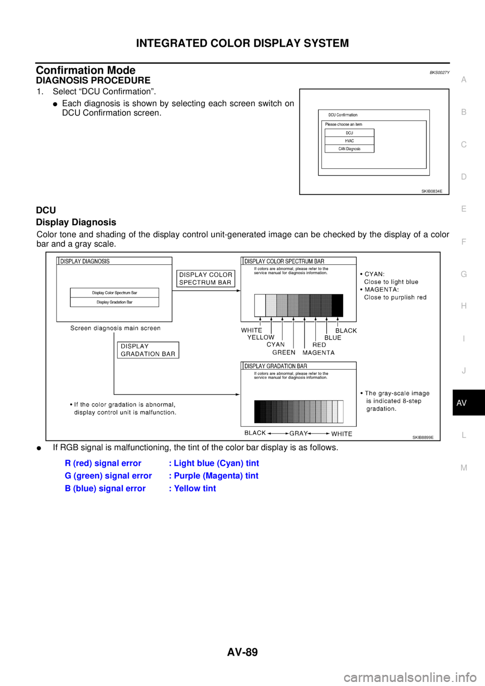
DCU
Display Diagnosis
Color tone and shading of the display control unit-generated image can be checked by the display of a color
bar and a gray scale.
�If RGB signal is malfunctioning, the tint of the color bar display is as follows.
SKIB0834E
R (red) signal error : Light blue (Cyan) tint
G (green) signal error : Purple (Magenta) tint
B (blue) signal error : Yellow tint
SKIB8899E
Page 618 of 3502

AV-90
INTEGRATED COLOR DISPLAY SYSTEM
Vehicle Signal
A comparison check can be made of each actual vehicle signal and
the signals recognized by the display control unit.
History of Error
Diagnosis results of self-diagnosis depend on if any error occurred
during the time after selecting “DCU Failure Diagnosis” until self-
diagnosis results is displayed.
Meanwhile, when an error occurs before selecting “DCU Failure
Diagnosis”, and if an error does not occur until self-diagnosis results
is displayed, a diagnosis result is judged as normal.
Consequently, a diagnosis needs to be performed with “History of
Error” for the past error that is not available with self-diagnosis.
“History of Error” stores error occurrences up to 50, and errors after
the 51st are displayed as the 50th.
SKIB0835E
Diagnosis item Display Condition Remarks
Speed SignalON When vehicle speed is more than 0 km/h (0 MPH)
Changes in indication may be delayed.
This is normal. OFF When vehicle speed is 0 km/h (0 MPH)
— Ignition switch in ACC position
LightON Lighting switch ON
—
OFF Lighting switch OFF
IGNON Ignition switch ON
—
OFF Ignition switch ACC position
ReverseON Selector lever in R position
Changes in indication may be delayed.
This is normal. OFF Selector lever in any position other than R position
— Ignition switch in ACC position
SKIB8900E
Page 635 of 3502

INTEGRATED COLOR DISPLAY SYSTEM
AV-107
C
D
E
F
G
H
I
J
L
MA
B
AV
Tint Is Strange for The RGB ImageBKS00288
Symptom: Tint of all RGB images is strange.
1. CHECK HARNESS
1. Turn ignition switch OFF.
2. Disconnect display control unit and display connectors.
3. Check the malfunctioning circuit according to the symptoms.
�Light blue (Cyan) tinged screen
Check continuity between display control unit harness connector
(A) M83 terminal 50 and display harness connector (B) M81 ter-
minal 17.
Check continuity between display control unit harness connector
(A) M83 terminal 50 and ground.
�Purple (Magenta) tinged screen
Check continuity between display control unit harness connector
(A) M83 terminal 52 and display harness connector (B) M81 ter-
minal 6.
Check continuity between display control unit harness connector
(A) M83 terminal 52 and ground.
�Yellow tinged screen
Check continuity between display control unit harness connector
(A) M83 terminal 54 and display harness connector (B) M81 ter-
minal 18.
Check continuity between display control unit harness connector
(A) M83 terminal 54 and ground.
OK or NG
OK >> GO TO 2.
NG >> Repair harness or connector.50 – 17 : Continuity should exist.
50 – Ground : Continuity should not exist.
SKIB7853E
52 – 6 : Continuity should exist.
52 – Ground : Continuity should not exist.
SKIB7854E
54 – 18 : Continuity should exist.
54 – Ground : Continuity should not exist.
SKIB7855E
Page 636 of 3502

AV-108
INTEGRATED COLOR DISPLAY SYSTEM
2. CHECK RGB SIGNAL
1. Connect display control unit and display connectors.
2. Turn ignition switch ON.
3. Start Confirmation mode. Refer to AV- 8 9 , "
Confirmation Mode" .
4. Display color bar by selecting “Display Color Spectrum Bar” on Display Diagnosis screen. Refer to AV- 8 9 ,
"Display Diagnosis" .
5. Check the malfunctioning circuit according to the symptoms.
�Light blue (Cyan) tinged screen
Check voltage waveform between display control unit harness
connector M83 terminal 50 and ground with CONSULT-ll or
oscilloscope.
�Purple (Magenta) tinged screen
Check voltage waveform between display control unit harness
connector M83 terminal 52 and ground with CONSULT-ll or
oscilloscope.
�Yellow tinged screen
Check voltage waveform between display control unit harness
connector M83 terminal 54 and ground with CONSULT-ll or
oscilloscope.
OK or NG
OK >> Replace display.
NG >> Replace display control unit.50 – Ground:
SKIB7856ESKIB7769E
52 – Ground:
SKIB7857ESKIB7770E
54 – Ground:
SKIB7858ESKIB7771E
Page 639 of 3502

INTEGRATED COLOR DISPLAY SYSTEM
AV-111
C
D
E
F
G
H
I
J
L
MA
B
AV
Example of Symptoms Possible No MalfunctionBKS0028D
For system operation information, refer to Owner's Manual.
DISPLAY
REAR VIEW MONITOR
Symptom Possible cause Possible solution
No image is displayed.The brightness is at the lowest setting. Adjust the brightness of the display.
The display is turned off. Turn on the display.
The screen is too dim. The move-
ment is slow.The temperature in the interior of the vehicle is
low.Wait until the interior of the vehicle has
warmed up.
Some pixels in the display are
darker or brighter than others.This condition is an inherent characteristic of
liquid crystal displays.This is not a malfunction.
Some menu items cannot be
selected.Some menu items become unavailable while
the vehicle is driven.Park the vehicle in a safe location, then oper-
ate the system.
Symptom Possible cause Possible solution
Rear view monitor image is not
shown.Selector lever is not set to R position. Shift the selector lever to R position.
Rear view monitor image is fuzzy.The front glass of the camera lens is dirty. Wipe it with a soft wet cloth lightly.
Adherence of raindrops or snow. Wipe it with a soft cloth lightly.
The lens is illuminated directly by sunlight or light
from headlight of cars behind.The fuzzy image recovers when the light is
covered.
Page 645 of 3502

BCS-3
C
D
E
F
G
H
I
J
L
MA
B
BCS
BCM (BODY CONTROL MODULE)PFP:284B2
System DescriptionBKS002EV
BCM (Body Control Module) controls the operation of various electrical units")
BCM (BODY CONTROL MODULE)
BCS-3
C
D
E
F
G
H
I
J
L
MA
B
BCS
BCM (BODY CONTROL MODULE)PFP:284B2
System DescriptionBKS002EV
BCM (Body Control Module) controls the operation of various electrical units installed on the vehicle.
BCM FUNCTION
BCM has combination switch reading function for reading the operation of combination switches (light, wiper
washer, turn signal) in addition to a function for controlling the operation of various electrical components. Also
it has an interface function allowing it to receive signals from the unified meter and A/C amp., and send signals
to ECM using CAN communication.
COMBINATION SWITCH READING FUNCTION
Description
�BCM reads combination switch (lighting switch, wiper switch) status, and controls various electrical com-
ponent, according to the results.
�BCM reads information of a maximum of 20 switches by combining 5 output terminals (OUTPUT 1-5) and
5 input terminals (INPUT 1-5).
Operation Description
�BCM activates transistors of output terminals (OUTPUT 1-5) periodically and, allows current to flow in
turn.
�If any (1 or more) switches are turned ON, circuit of output terminals (OUTPUT 1-5) and input terminals
(INPUT 1-5) becomes active.
�At this time, transistors of output terminals (OUTPUT 1-5) are activated to allow current to flow. When volt-
age of input terminals (INPUT 1-5) corresponding to that switch changes, interface in BCM detects volt-
age change, and BCM determines that switch is ON.
SKIB8812E
Page 647 of 3502
BCM (BODY CONTROL MODULE)
BCS-5
C
D
E
F
G
H
I
J
L
MA
B
BCS
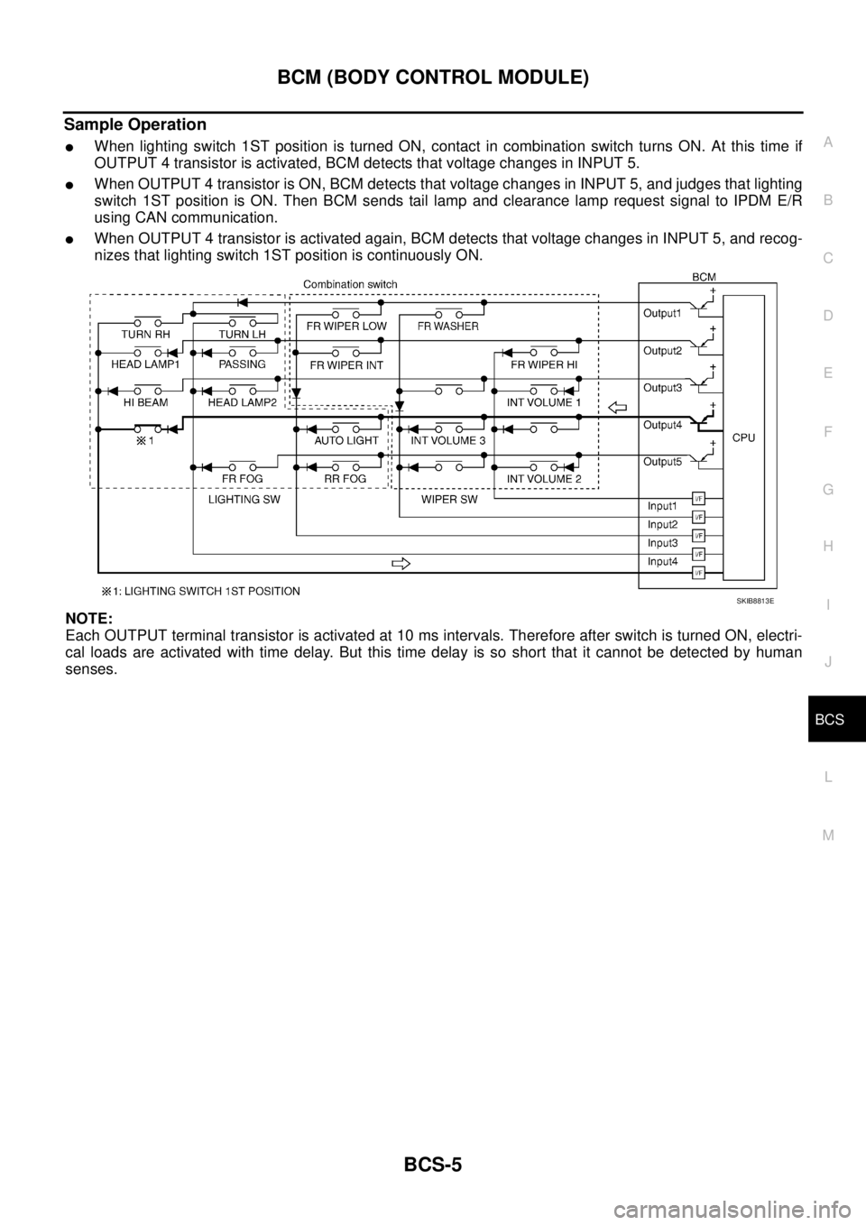
Sample Operation
�When lighting switch 1ST position is turned ON, contact in combination switch turns ON. At this time if
OUTPUT 4 transistor is activated, BCM detects that voltage changes in INPUT 5.
�When OUTPUT 4 transistor is ON, BCM detects that voltage changes in INPUT 5, and judges that lighting
switch 1ST position is ON. Then BCM sends tail lamp and clearance lamp request signal to IPDM E/R
using CAN communication.
�When OUTPUT 4 transistor is activated again, BCM detects that voltage changes in INPUT 5, and recog-
nizes that lighting switch 1ST position is continuously ON.
NOTE:
Each OUTPUT terminal transistor is activated at 10 ms intervals. Therefore after switch is turned ON, electri-
cal loads are activated with time delay. But this time delay is so short that it cannot be detected by human
senses.
SKIB8813E