Page 403 of 3502

AIR CONDITIONER CONTROL
ATC-25
C
D
E
F
G
H
I
K
L
MA
B
AT C
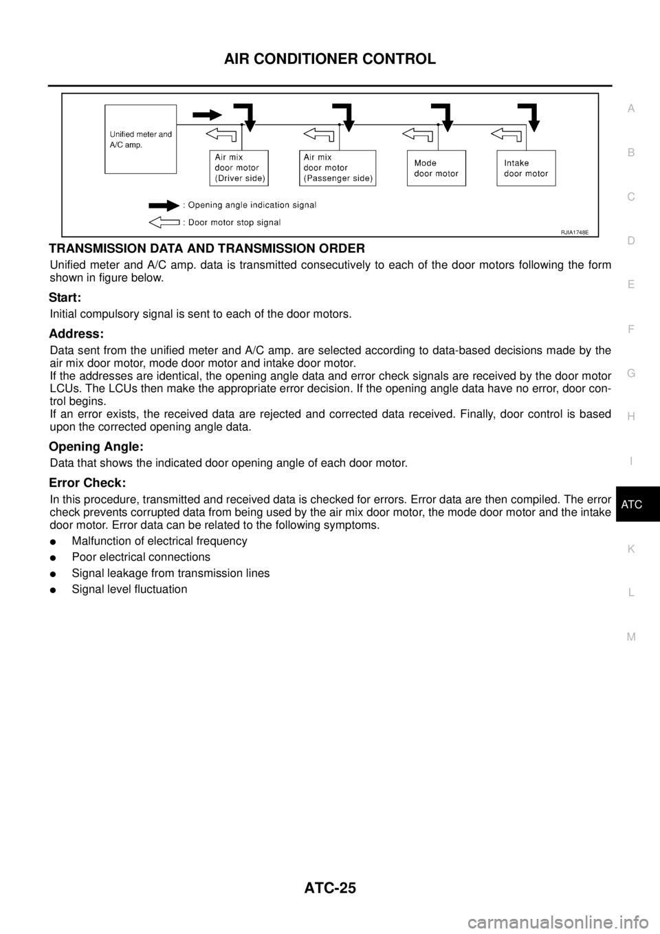
TRANSMISSION DATA AND TRANSMISSION ORDER
Unified meter and A/C amp. data is transmitted consecutively to each of the door motors following the form
shown in figure below.
Start:
Initial compulsory signal is sent to each of the door motors.
Address:
Data sent from the unified meter and A/C amp. are selected according to data-based decisions made by the
air mix door motor, mode door motor and intake door motor.
If the addresses are identical, the opening angle data and error check signals are received by the door motor
LCUs. The LCUs then make the appropriate error decision. If the opening angle data have no error, door con-
trol begins.
If an error exists, the received data are rejected and corrected data received. Finally, door control is based
upon the corrected opening angle data.
Opening Angle:
Data that shows the indicated door opening angle of each door motor.
Error Check:
In this procedure, transmitted and received data is checked for errors. Error data are then compiled. The error
check prevents corrupted data from being used by the air mix door motor, the mode door motor and the intake
door motor. Error data can be related to the following symptoms.
�Malfunction of electrical frequency
�Poor electrical connections
�Signal leakage from transmission lines
�Signal level fluctuation
RJIA1748E
Page 404 of 3502

ATC-26
AIR CONDITIONER CONTROL
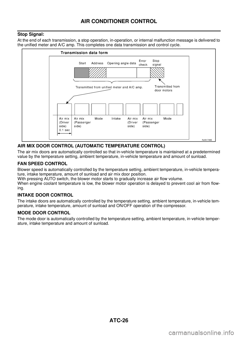
Stop Signal:
At the end of each transmission, a stop operation, in-operation, or internal malfunction message is delivered to
the unified meter and A/C amp. This completes one data transmission and control cycle.
AIR MIX DOOR CONTROL (AUTOMATIC TEMPERATURE CONTROL)
The air mix doors are automatically controlled so that in-vehicle temperature is maintained at a predetermined
value by the temperature setting, ambient temperature, in-vehicle temperature and amount of sunload.
FAN SPEED CONTROL
Blower speed is automatically controlled by the temperature setting, ambient temperature, in-vehicle tempera-
ture, intake temperature, amount of sunload and air mix door position.
With pressing AUTO switch, the blower motor starts to gradually increase air flow volume.
When engine coolant temperature is low, the blower motor operation is delayed to prevent cool air from flow-
ing.
INTAKE DOOR CONTROL
The intake doors are automatically controlled by the temperature setting, ambient temperature, in-vehicle tem-
perature, intake temperature, amount of sunload and ON/OFF operation of the compressor.
MODE DOOR CONTROL
The mode door is automatically controlled by the temperature setting, ambient temperature, in-vehicle temper-
ature, intake temperature and amount of sunload.
RJIA1749E
Page 405 of 3502
AIR CONDITIONER CONTROL
ATC-27
C
D
E
F
G
H
I
K
L
MA
B
AT C
MAGNET CLUTCH CONTROL
When A/C switch is pressed (with FAN ON), press DEF switch, unified meter and A/C amp. transmits com-
pressor ON signal to BCM.
BCM sends compressor ON signal to ECM, via CAN communication.
ECM judges whether compressor can be turned ON, based on each sensor status (refrigerant pressure sen-
sor signal, throttle angle, etc.). If it judges compressor can be turned ON, it sends compressor ON signal to
IPDM E/R, via CAN communication.
Upon receipt of compressor ON signal from ECM, IPDM E/R turns air conditioner relay ON to operate com-
pressor.
SELF-DIAGNOSIS SYSTEM
The self-diagnosis system is built into the unified meter and A/C amp. to quickly locate the cause of malfunc-
tions.
SJIA1648E
Page 406 of 3502
ATC-28
AIR CONDITIONER CONTROL
Description of Control SystemBJS000FL
The control system consists of input sensors, switches, the unified meter and A/C amp. (microcomputer) and
outputs. The relationship of these components is shown in the figure below:
SJIA1649E
Page 408 of 3502

ATC-30
AIR CONDITIONER CONTROL
�When fan control switch (DOWN) is pressed for approximately 2 seconds or longer or press fan control
switch when blower fan motor operates at 1st speed, A/C system will turn OFF (The compressor and
blower are OFF, the intake doors and the mode doors are automatically controlled).
INTAKE SWITCH
�When intake switch is ON, FRE LED turns ON, and air inlet is fixed to FRE.
�When press intake switch again, REC LED turns ON, and air inlet is fixed to REC.
�When intake switch is pressed for approximately 1.5 seconds or longer, FRE and REC LEDs blink twice.
Then, automatic control mode is entered. Inlet status is displayed by LED even during automatic con-
trolled.
�When FRE LED is turned ON, shifting mode position to D/F or DEF, or when compressor is turned from
ON to OFF, intake switch is automatically turned OFF (fixed to FRE mode). REC mode can be re-entered
by pressing intake switch again, and then compressor is turned ON. (Except D/F or DEF position)
MODE SWITCH
The air discharge outlets is controlled with this switch.
DEFROSTER (DEF) SWITCH
Mode doors are set to the defrost position with this switch. Also, intake doors are set to the outside air position,
and compressor turns ON.
REAR WINDOW DEFOGGER SWITCH
When illumination is ON, rear window is defogged.
DUAL SWITCH
�When the DUAL switch indicator is illuminated, the driver-side and passenger-side temperature can each
be set independently.
�When the DUAL switch indicator is not illuminated, the driver-side setting temperature is applied to both
sides.
Fail-safe FunctionBJS000FN
If a communication error exists between the unified meter and A/C amp. and the A/C and AV switch for 30 sec-
onds or longer, air conditioner is controlled under the following conditions:
Compressor : ON
Air outlet : AUTO
Air inlet : FRE (Fresh)
Blower fan speed : AUTO
Set temperature : Setting before communication error occurs
Display : OFF
Page 422 of 3502
ATC-44
TROUBLE DIAGNOSIS
Auto Amp. Terminals and Reference ValueBJS000FW
Measure voltage between each terminal and ground by referring ter-
minals and reference value for unified meter and A/C amp.
PIN CONNECTOR TERMINAL LAYOUT
TERMINALS AND REFERENCE VALUE FOR UNIFIED METER AND A/C AMP.
RJIA2732E
RJIA2734E
Te r m i n a l
No.Wire
colorItemIgnition
switchConditionVoltag e
(V)
1 L CAN-H — — —
11 P C A N - L — — —
21 Y/R Power supply from BATT OFF — Battery voltage
22 G Power supply from IGN ON — Battery voltage
29 B Ground (Power) ON — Approx. 0
30 B Ground ON — Approx. 0
35 V Power supply from ACC ACC — Battery voltage
39 O/B Ambient sensor — — —
40 LG In-vehicle sensor — — —
41 R/W Intake sensor — — —
42 SB Compressor ON signal ONA/C switch: ON (Blower motor
operates.)Approx. 0
OFF switch: ON (A/C System:
OFF)
43 L/R A/C LAN signal ON —
SJIA1423J
SJIA1453J
Page 425 of 3502

TROUBLE DIAGNOSIS
ATC-47
C
D
E
F
G
H
I
K
L
MA
B
AT C
FUNCTION CONFIRMATION PROCEDURE
1. SET IN SELF-DIAGNOSIS MODE
1. Turn ignition switch ON.
2. Set in self-diagnosis mode as follows. Within 10 seconds after starting engine (ignition switch is turned
ON.), press A/C switch for at least 5 seconds.
CAUTION:
�Press A/C switch after indicating LED of intake switch.
�If battery voltage drops below 12 V during diagnosis STEP-3, door motor speed becomes slower
and as a result, the system may generate an error even when operation is normal. To avoid this,
start engine before performing this diagnosis.
�Former STEP-1 (LEDs and display screen are checked) does not exist in this self-diagnosis func-
tion.
>> GO TO 2.
2. STEP-2: SENSOR CIRCUITS ARE CHECKED FOR OPEN OR SHORT CIRCUIT
Does code No. 20 appear on the display?
YES >> GO TO 3.
NO >> GO TO 13.
3. CHECK TO ADVANCE SELF-DIAGNOSIS STEP-3
Press temperature control switch (UP, driver side).
Advance to self
-diagnosis STEP-3?
YES >> GO TO 4.
NO >> Replace A/C and AV switch. (Temperature control switch is malfunctioning.)
4. CHECK TO RETURN SELF-DIAGNOSIS STEP-2
Press temperature control switch (DOWN, driver side).
Return to self
-diagnosis STEP-2?
YES >> GO TO 5.
NO >> Malfunctioning A/C and AV switch or unified meter and A/C amp. Refer to AT C - 9 4 , "
Self-diagno-
sis" .
5. STEP-3: MODE DOOR AND INTAKE DOOR POSITIONS ARE CHECKED
Press temperature control switch (UP, driver side).
Does code No. 30 appear on the display?
YES >> GO TO 6.
NO >> GO TO 14.
RHA970DB
RHA869DD
Page 428 of 3502

ATC-50
TROUBLE DIAGNOSIS
12. CHECK CAN COMMUNICATION ERROR
1. Press intake switch.
2. CAN communication error between the unified meter and A/C
amp. and the display unit or display control unit can be detected
as self-diagnosis results. (If plural errors occur, the display of
each error will blink twice for 0-5 second intervals.) .
OK or NG
OK >> 1. Turn ignition switch OFF or AUTO switch ON.
2. INSPECTION END
NG >> Go to CAN communication. Refer to LAN-49, "
CAN Sys-
tem Specification Chart" .
�Unified meter and A/C amp. - Display unit or Display
control unit.
13. CHECK MALFUNCTIONING SENSOR
Refer to the following chart for malfunctioning code No.
(If two or more sensors malfunction, corresponding code Nos. blink respectively twice.)
*1: Perform self-diagnosis STEP-2 under sunshine.
When performing indoors, aim a light (more than 60 W) at sunload sensor, otherwise code No. 25 will indicate
despite that sunload sensor is functioning properly.
*2: AT C - 9 6 , "
DIAGNOSIS PROCEDURE FOR AMBIENT SENSOR" .
*3: ATC-100, "
DIAGNOSIS PROCEDURE FOR IN-VEHICLE SENSOR" .
*4: ATC-105, "
DIAGNOSIS PROCEDURE FOR INTAKE SENSOR" .
*5: ATC-102, "
DIAGNOSIS PROCEDURE FOR SUNLOAD SENSOR" .
*6: AT C - 6 8 , "
DIAGNOSIS PROCEDURE FOR AIR MIX DOOR MOTOR PBR" .
>> INSPECTION END
RJIA1762E
Code No. Malfunctioning sensor (Including circuits) Reference page
21 / −21 Ambient sensor *2
22 / −22 In-vehicle sensor *3
24 / −24 Intake sensor *4
25 / −25
Sunload sensor
*1*5
26 / −26 Air mix door motor PBR (Driver side)
*6
27 / −27 Air mix door motor PBR (Passenger side)
PJIA0022E