Page 27 of 3502
A/T CONTROL SYSTEM
AT-19
D
E
F
G
H
I
J
K
L
MA
B
AT
POWER TRANSMISSION
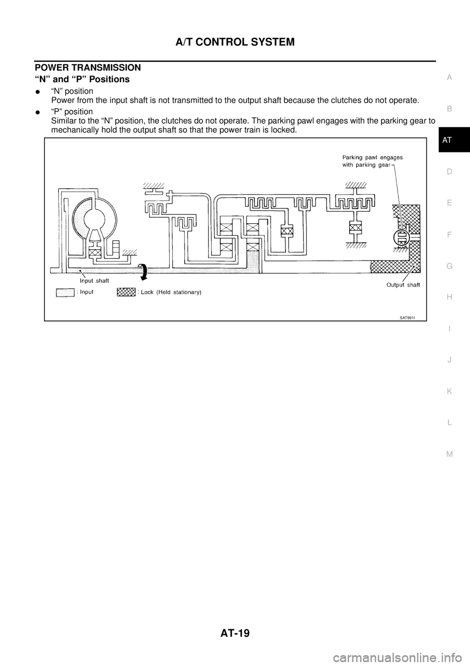
“N” and “P” Positions
�“N” position
Power from the input shaft is not transmitted to the output shaft because the clutches do not operate.
�“P” position
Similar to the “N” position, the clutches do not operate. The parking pawl engages with the parking gear to
mechanically hold the output shaft so that the power train is locked.
SAT991I
Page 30 of 3502
AT-22
A/T CONTROL SYSTEM
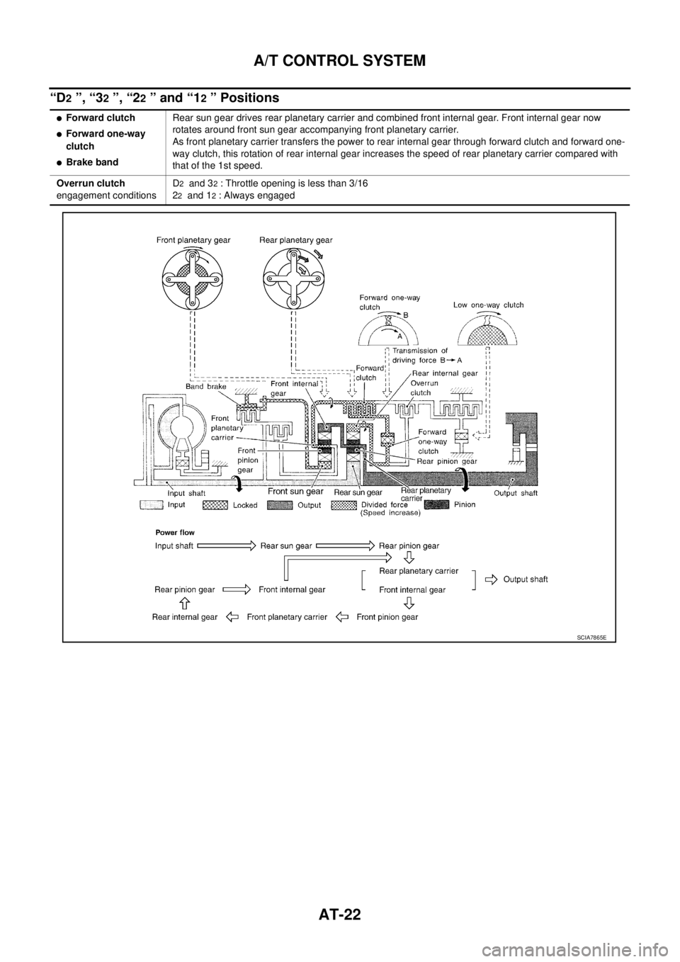
“D2 ”, “32 ”, “22 ” and “12 ” Positions
�Forward clutch
�Forward one-way
clutch
�Brake bandRear sun gear drives rear planetary carrier and combined front internal gear. Front internal gear now
rotates around front sun gear accompanying front planetary carrier.
As front planetary carrier transfers the power to rear internal gear through forward clutch and forward one-
way clutch, this rotation of rear internal gear increases the speed of rear planetary carrier compared with
that of the 1st speed.
Overrun clutch
engagement conditionsD
2 and 32 : Throttle opening is less than 3/16
2
2 and 12 : Always engaged
SCIA7865E
Page 31 of 3502
A/T CONTROL SYSTEM
AT-23
D
E
F
G
H
I
J
K
L
MA
B
AT
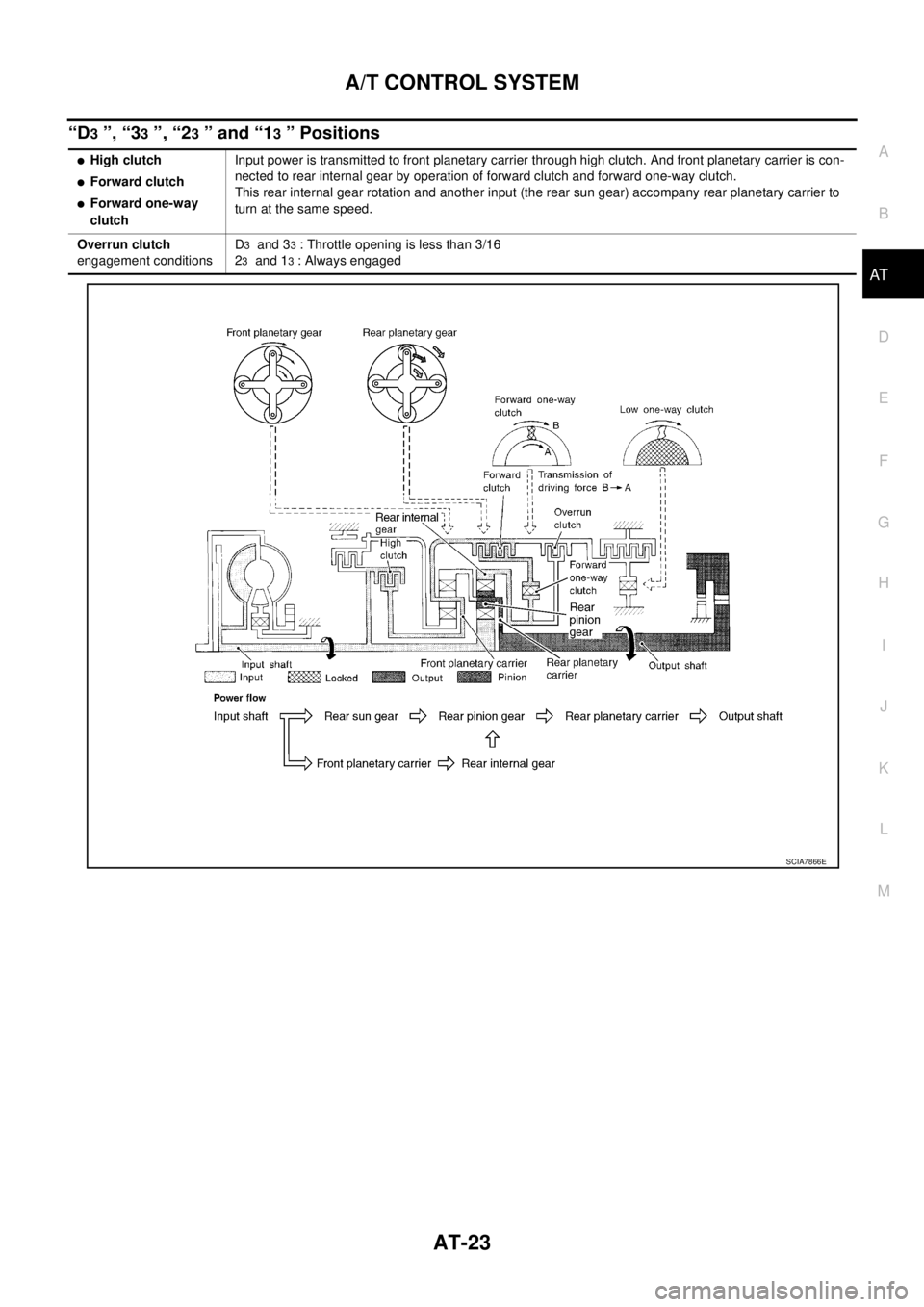
“D3 ”, “33 ”, “23 ” and “13 ” Positions
�High clutch
�Forward clutch
�Forward one-way
clutchInput power is transmitted to front planetary carrier through high clutch. And front planetary carrier is con-
nected to rear internal gear by operation of forward clutch and forward one-way clutch.
This rear internal gear rotation and another input (the rear sun gear) accompany rear planetary carrier to
turn at the same speed.
Overrun clutch
engagement conditionsD
3 and 33 : Throttle opening is less than 3/16
2
3 and 13 : Always engaged
SCIA7866E
Page 32 of 3502
AT-24
A/T CONTROL SYSTEM
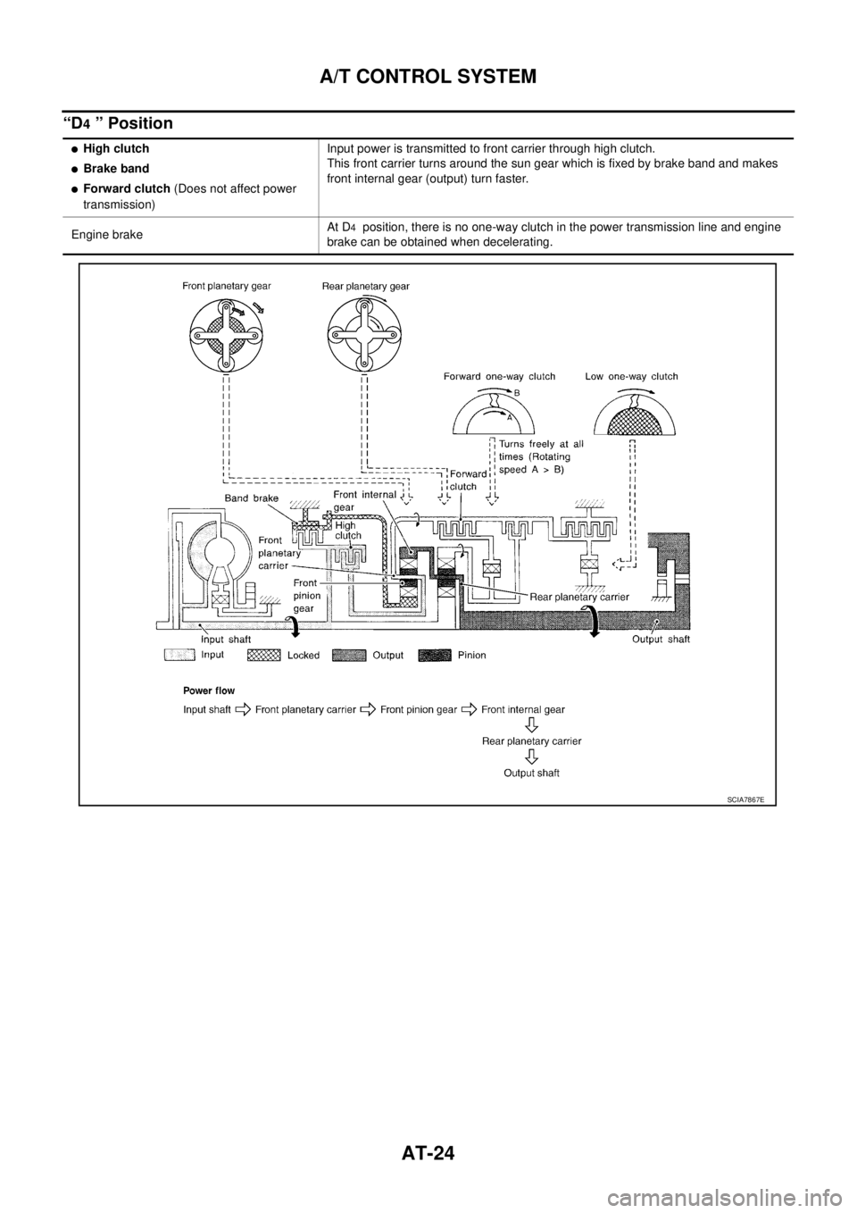
“D4 ” Position
�High clutch
�Brake band
�Forward clutch (Does not affect power
transmission)Input power is transmitted to front carrier through high clutch.
This front carrier turns around the sun gear which is fixed by brake band and makes
front internal gear (output) turn faster.
Engine brakeAt D
4 position, there is no one-way clutch in the power transmission line and engine
brake can be obtained when decelerating.
SCIA7867E
Page 33 of 3502
A/T CONTROL SYSTEM
AT-25
D
E
F
G
H
I
J
K
L
MA
B
AT
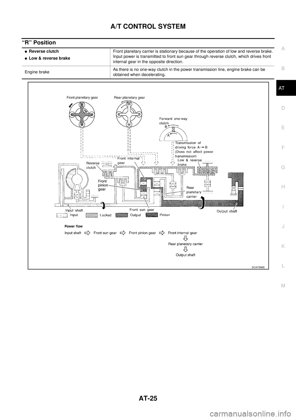
“R” Position
�Reverse clutch
�Low & reverse brakeFront planetary carrier is stationary because of the operation of low and reverse brake.
Input power is transmitted to front sun gear through reverse clutch, which drives front
internal gear in the opposite direction.
Engine brakeAs there is no one-way clutch in the power transmission line, engine brake can be
obtained when decelerating.
SCIA7868E
Page 34 of 3502

AT-26
A/T CONTROL SYSTEM
TCM FunctionBCS000ZP
The function of the TCM is to:
�Receive input signals sent from various switches and sensors.
�Determine required line pressure, shifting point, lock-up operation, and engine brake operation.
�Send required output signals to the respective solenoids.
CONTROL SYSTEM OUTLINE
The automatic transmission senses vehicle operating conditions through various sensors or signals. It always
controls the optimum shift position and reduces shifting and lock-up shocks.
CONTROL SYSTEM DIAGRAM
SWITCHES & SENSORS
�TCM
�ACTUATORS
PNP switch
Accelerator pedal position signal
Closed throttle position signal
Wide open throttle position signal
Engine speed signal
A/T fluid temperature sensor
Revolution sensor
Turbine revolution sensor (power
train revolution sensor)
Vehicle speed signal
3rd position switch signal
Stop lamp switch signalShift control
Line pressure control
Lock-up control
Overrun clutch control
Timing control
Fail-safe control
Self-diagnosis
CONSULT-II communication line
control
CAN systemShift solenoid valve A
Shift solenoid valve B
Overrun clutch solenoid valve
Torque converter clutch solenoid
valve
Line pressure solenoid valve
A/T CHECK indicator lamp
SCIA7869E
Page 35 of 3502
 is a serial communication line for real time application. It is an on-ve")
A/T CONTROL SYSTEM
AT-27
D
E
F
G
H
I
J
K
L
MA
B
AT
CAN CommunicationBCS000ZQ
SYSTEM DESCRIPTION
CAN (Controller Area Network) is a serial communication line for real time application. It is an on-vehicle mul-
tiplex communication line with high data communication speed and excellent error detection ability. Many elec-
tronic control units are equipped onto a vehicle, and each control unit shares information and links with other
control units during operation (not independent). In CAN communication, control units are connected with 2
communication lines (CAN H line, CAN L line) allowing a high rate of information transmission with less wiring.
Each control unit transmits/receives data but selectively reads required data only. For details, refer to LAN-49,
"CAN System Specification Chart" .
Input/Output Signal of TCMBCS000ZR
*1: Spare for vehicle speed sensor·A/T (revolution sensor)
*2: Spare for accelerator pedal position signal
*3: If these input and output signals are different, the TCM triggers the fail-safe function.
*4: Used as a condition for starting self-diagnostics; if self-diagnostics are not started, it is judged that there is some kind of error.
*5: Input by CAN communications.
*6: Output by CAN communications.Control itemLine
pressure
controlVehicle
speed
controlShift
controlLock-up
controlEngine
brake
controlFail-safe
functionSelf-diag-
nostics
function
InputAccelerator pedal position signal
(*5)XXXXX(*3) XX
Vehicle speed sensor A/T
(Revolution sensor)XXXXX(*3) XX
Vehicle speed sensor MTR
(*1)XXXX X
Closed throttle position signal
(*5)(*2) X(*2) XXX(*4) X
Wide open throttle position signal
(*5)(*2) X (*2) X (*4) X
Turbine revolution sensor (Power
train revolution sensor)XX X XX
Engine speed signal X X X X
PNP switch XXXXX(*3) X(*4) X
Stop lamp switch signal
(*5)XX (*4) X
A/T fluid temperature sensors X X X X X X
3rd position switch signal
(*5)XXXX (*4) X
TCM power supply voltage signal X X X X
Out-
putShift solenoid valve A/B X (*3) X X
Line pressure solenoid X (*3) X X
Torque converter clutch solenoid
valveX(*3) XX
Overrun clutch solenoid valve X X (*3) X X
A/T CHECK indicator lamp
(*6)X
Page 38 of 3502

AT-30
A/T CONTROL SYSTEM
CONTROL OF SHIFT VALVES A AND B
Pilot pressure generated by the operation of shift solenoid valves A and B is applied to the end face of shift
valves A and B.
The figure above shows the operation of shift valve B. When the shift solenoid valve is “ON”, pilot pressure
applied to the end face of the shift valve overcomes spring force, moving the valve upward.
Lock-up ControlBCS000ZU
The torque converter clutch piston in the torque converter is locked to eliminate torque converter slip to
increase power transmission efficiency. The solenoid valve is controlled by an ON-OFF duty signal sent from
the TCM. The signal is converted to an oil pressure signal which controls the torque converter clutch piston.
CONDITIONS FOR LOCK-UP OPERATION
When vehicle is driven in 3rd and 4th gear position, vehicle speed and throttle opening are detected. If the
detected values fall within the lock-up zone memorized in the TCM, lock-up is performed.
TORQUE CONVERTER CLUTCH SOLENOID VALVE CONTROL
Lock-up Control System Diagram
SAT009J
Selector lever “D” position “3” position
Gear position D
4 , D333
Vehicle speed sensor More than set value
accelerator pedal position sensor Less than set opening
Closed throttle position signal OFF
A/T fluid temperature sensor More than 20°C (68°F)
SCIA5623E