Page 2814 of 3502
 controls front fog lamp operation.
�IPDM E/")
LT-126
FRONT FOG LAMP
FRONT FOG LAMPPFP:26150
Component Parts and Harness Connector LocationBKS001OP
System DescriptionBKS001OQ
�BCM (Body Control Module) controls front fog lamp operation.
�IPDM E/R (Intelligent Power Distribution Module Engine Room) operates front fog lamp according to CAN
communication signals from BCM.
�Unified meter and A/C amp. operates front fog lamp indicator according to CAN communication signals.
OUTLINE
Power is supplied at all times
�to ignition relay (located in IPDM E/R), from battery direct,
�through 15A fuse (No. 88, located in IPDM E/R)
�to front fog lamp relay (located in IPDM E/R),
�through 15A fuse (No. 71, located in IPDM E/R)
�to CPU (central processing unit) located in IPDM E/R,
�through 15A fuse (No. 78, located in IPDM E/R)
�to CPU located in IPDM E/R,
�through 50A fusible link (letter M, located in fuse and fusible link block)
�to BCM terminal 55,
�through 15A fuse [No. 17, located in fuse block (J/B)]
�to BCM terminal 42 and
�to combination meter terminal 7.
PKID0046E
Page 2815 of 3502
,
�through 10A fuse [No. 1, located in")
FRONT FOG LAMP
LT-127
C
D
E
F
G
H
I
J
L
MA
B
LT
When the ignition switch is in ON or START position, power is supplied
�to ignition relay (located in IPDM E/R),
�through 10A fuse [No. 1, located in fuse block (J/B)]
�to BCM terminal 38,
�through 10A fuse [No. 14, located in fuse block (J/B)]
�to combination meter terminal 8.
When the ignition switch is in ACC or ON position, power is supplied
�through 10A fuse [No. 6, located in fuse block (J/B)]
�to BCM terminal 11.
Ground is supplied
�to BCM terminal 52 and
�to combination meter terminals 10, 11 and 12
�through grounds M71 and M72,
�to IPDM E/R terminals 38 and 60
�through grounds E1 and E31.
FRONT FOG LAMP OPERATION
When the lighting switch is in front fog lamp ON position and also in 1ST or 2ND position or AUTO position
(headlamp is ON), BCM detects FR FOG (ON) and the HEAD LAMP1, 2 (ON) or the AUTO LIGHT (ON) by
BCM combination switch reading function. And then, BCM sends front fog lamp request signal (ON) through
CAN communication.
When receiving front fog lamp request signal (ON), IPDM E/R turns ON front fog lamp relay in IPDM E/R. And
then, front fog lamp go ON. IPDM E/R supplies power
�through IPDM E/R terminal 36
�to front fog lamp RH terminal 1,
�through IPDM E/R terminal 37
�to front fog lamp LH terminal 1.
Ground is supplied
�to front fog lamp RH and LH terminals 2
�through grounds E1 and E31.
With power and ground supplied, the front fog lamp illuminates.
Unified meter and A/C amp. receives front fog lamp request signal (ON) through CAN communication, and
make front fog indicator go ON in combination meter.
COMBINATION SWITCH READING FUNCTION
Refer to BCS-3, "COMBINATION SWITCH READING FUNCTION" .
EXTERIOR LAMP BATTERY SAVER CONTROL
Refer to LT- 1 9 7 , "EXTERIOR LAMP BATTERY SAVER CONTROL" .
CAN Communication System DescriptionBKS001OR
CAN (Controller Area Network) is a serial communication line for real time application. It is an on-vehicle mul-
tiplex communication line with high data communication speed and excellent error detection ability. Many elec-
tronic control units are equipped onto a vehicle, and each control unit shares information and links with other
control units during operation (not independent). In CAN communication, control units are connected with 2
communication lines (CAN H line, CAN L line) allowing a high rate of information transmission with less wiring.
Each control unit transmits/receives data but selectively reads required data only.
CAN Communication UnitBKS001OS
Refer to LAN-49, "CAN System Specification Chart" .
Page 2821 of 3502

FRONT FOG LAMP
LT-133
C
D
E
F
G
H
I
J
L
MA
B
LT
Terminals and Reference Values for IPDM E/RBKS001OW
How to Perform Trouble DiagnosisBKS001OX
1. Confirm the symptom or customer complaint.
2. Understand operation description and function description. Refer to LT- 1 2 6 , "
System Description" .
3. Perform the Preliminary Check. Refer to LT- 1 3 3 , "
Preliminary Check" .
4. Check symptom and repair or replace the cause of malfunction.
5. Does the front fog lamp operate normally? If YES, GO TO 6. If NO, GO TO 4.
6. INSPECTION END
Preliminary CheckBKS001OY
CHECK POWER SUPPLY AND GROUND CIRCUIT
1. CHECK FUSES AND FUSIBLE LINK
Check for blown fuses and fusible link.
Refer to LT-129, "Wiring Diagram — F/FOG —" .
OK or NG
OK >> GO TO 2.
NG >> If fuse or fusible link is blown, be sure to eliminate cause of malfunction before installing new fuse
or fusible link. Refer to PG-3, "
POWER SUPPLY ROUTING CIRCUIT" .
Terminal
No.Wire
colorSignal nameMeasuring condition
Reference value
Ignition
switchOperation or condition
36 W/R Front fog lamp (RH) ONLighting switch front fog lamp ON
position
(when lighting switch is 1ST position)OFF Approx. 0 V
ON Battery voltage
37 L/Y Front fog lamp (LH) ONLighting switch front fog lamp ON
position
(when lighting switch is 1ST position)OFF Approx. 0 V
ON Battery voltage
38 B Ground ON — Approx. 0 V
48 L CAN-H — — —
49 P CAN-L — — —
60 B Ground ON — Approx. 0V
Unit Power source Fuse and fusible link No.
BCMBatteryM
17
Ignition switch ACC or ON position 6
Ignition switch ON or START position 1
IPDM E/R Battery 88
Page 2830 of 3502
LT-142
REAR FOG LAMP
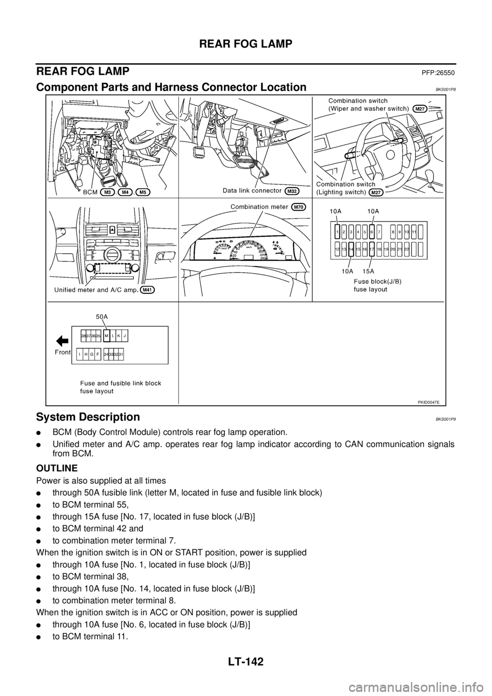
REAR FOG LAMPPFP:26550
Component Parts and Harness Connector LocationBKS001P8
System DescriptionBKS001P9
�BCM (Body Control Module) controls rear fog lamp operation.
�Unified meter and A/C amp. operates rear fog lamp indicator according to CAN communication signals
from BCM.
OUTLINE
Power is also supplied at all times
�through 50A fusible link (letter M, located in fuse and fusible link block)
�to BCM terminal 55,
�through 15A fuse [No. 17, located in fuse block (J/B)]
�to BCM terminal 42 and
�to combination meter terminal 7.
When the ignition switch is in ON or START position, power is supplied
�through 10A fuse [No. 1, located in fuse block (J/B)]
�to BCM terminal 38,
�through 10A fuse [No. 14, located in fuse block (J/B)]
�to combination meter terminal 8.
When the ignition switch is in ACC or ON position, power is supplied
�through 10A fuse [No. 6, located in fuse block (J/B)]
�to BCM terminal 11.
PKID0047E
Page 2835 of 3502

REAR FOG LAMP
LT-147
C
D
E
F
G
H
I
J
L
MA
B
LT
How to Proceed With Trouble DiagnosisBKS001PE
1. Confirm the symptom or customer complaint.
2. Understand operation description and function description. Refer to LT- 1 4 2 , "
System Description" .
3. Perform the Preliminary Check. Refer toLT- 1 4 7 , "
Preliminary Check" .
4. Check symptom and repair or replace the cause of malfunction.
5. Does the rear fog lamp operate normally? If YES, GO TO 6. If NO, GO TO 4.
6. INSPECTION END
Preliminary CheckBKS001PF
CHECK POWER SUPPLY AND GROUND CIRCUIT
1. CHECK FUSES AND FUSIBLE LINK
Check for blown fuses and fusible link.
Refer to LT-144, "Wiring Diagram — R/FOG —" .
OK or NG
OK >> GO TO 2.
NG >> If fuse or fusible link is blown, be sure to eliminate cause of malfunction before installing new fuse
or fusible link. Refer to PG-3, "
POWER SUPPLY ROUTING CIRCUIT" .
2. CHECK POWER SUPPLY CIRCUIT
1. Turn ignition switch OFF.
2. Disconnect BCM connector.
3. Check voltage between BCM harness connector and ground.
OK or NG
OK >> GO TO 3.
NG >> Repair harness or connector.
Unit Power source Fuse and fusible link No.
BCMBatteryM
17
Ignition switch ACC or ON position 6
Ignition switch ON or START position 1
Terminals Ignition switch position
(+)
(-) OFF ACC ON
BCM
connectorTerminal
M311
GroundApprox. 0 VBattery
voltageBattery
voltage
38 Approx. 0 V Approx. 0 VBattery
voltage
M442Battery
voltageBattery
voltageBattery
voltage
55Battery
voltageBattery
voltageBattery
voltage
PKIA5204E
Page 2840 of 3502
")
LT-152
TURN SIGNAL AND HAZARD WARNING LAMPS
TURN SIGNAL AND HAZARD WARNING LAMPSPFP:26120
Component Parts and Harness Connector LocationBKS001PM
System DescriptionBKS001PN
�BCM (Body Control Module) controls turn signal lamp (RH and LH) and hazard warning lamp operation.
�Unified meter and A/C amp. operates turn (RH and LH) indicator according to CAN communication sig-
nals from BCM.
OUTLINE
Power is supplied at all times
�through 50A fusible link (letter M, located in fuse and fusible link block)
�to BCM terminal 55,
�through 15A fuse [No. 17, located in fuse block (J/B)]
�to BCM terminal 42 and
�to combination meter terminal 7.
With the ignition switch in the ON or START position, power is supplied
�through 10A fuse [No. 1, located in fuse block (J/B)]
�to BCM terminal 38,
�through 10A fuse [No. 14, located in fuse block (J/B)]
�to combination meter terminal 8.
With the ignition switch in the ACC or ON position, power is supplied
�through 10A fuse [No. 6, located in fuse block (J/B)]
�to BCM terminal 11.
PKIB0249E
Page 2849 of 3502

TURN SIGNAL AND HAZARD WARNING LAMPS
LT-161
C
D
E
F
G
H
I
J
L
MA
B
LT
Preliminary CheckBKS001PU
CHECK POWER SUPPLY AND GROUND CIRCUIT
1. CHECK FUSES AND FUSIBLE LINK
Check for blown fuses and fusible link.
Refer to LT-156, "Wiring Diagram — TURN —" .
OK or NG
OK >> GO TO 2.
NG >> If fuse or fusible link is blown, be sure to eliminate cause of malfunction before installing new fuse
or fusible link. Refer to PG-3, "
POWER SUPPLY ROUTING CIRCUIT" .
2. CHECK POWER SUPPLY CIRCUIT
1. Turn ignition switch OFF.
2. Disconnect BCM connector.
3. Check voltage between BCM harness connector and ground.
OK or NG
OK >> GO TO 3.
NG >> Repair harness or connector.
3. CHECK GROUND CIRCUIT
Check continuity between BCM harness connector and ground.
OK or NG
OK >> INSPECTION END
NG >> Repair harness or connector.
Unit Power source Fuse and fusible link No.
BCMBatteryM
17
Ignition switch ACC or ON position 6
Ignition switch ON or START position 1
Terminals Ignition switch position
(+)
(-) OFF ACC ON
BCM
connectorTerminal
M311
GroundApprox. 0 VBattery
voltageBattery
voltage
38 Approx. 0 V Approx. 0 VBattery
voltage
M442Battery
voltageBattery
voltageBattery
voltage
55Battery
voltageBattery
voltageBattery
voltage
PKIA5204E
Connector Terminal
GroundContinuity
M4 52 Yes
PKIA6256E
Page 2884 of 3502

LT-196
PARKING, LICENSE PLATE AND TAIL LAMPS
PARKING, LICENSE PLATE AND TAIL LAMPSPFP:26550
Component Parts and Harness Connector LocationBKS001QJ
System DescriptionBKS001QK
�BCM (Body Control Module) controls parking, license plate and tail lamps operation.
�IPDM E/R (Intelligent Power Distribution Module Engine Room) operates parking, license plate and tail
lamps according to CAN communication signals from BCM.
�Unified meter and A/C amp. operates tail lamp indicator according to CAN communication signals from
BCM.
OUTLINE
Power is supplied at all times
�to ignition relay (located in IPDM E/R), from battery direct,
�through 15A fuse (No. 71, located in IPDM E/R)
�to tail lamp relay (located in IPDM E/R) and
�to CPU (central processing unit) in IPDM E/R,
�through 15A fuse (No. 78, located in IPDM E/R)
�to CPU in IPDM E/R,
�through 50A fusible link (letter M, located in fuse and fusible link block)
�to BCM terminal 55,
�through 15A fuse [No. 17, located in fuse block (J/B)]
�to BCM terminal 42 and
�to combination meter terminal 7,
�through 10A fuse [No.19, located in fuse block (J/B)]
PKID0048E