Page 799 of 3502

NATS(NISSAN ANTI-THEFT SYSTEM)
BL-141
C
D
E
F
G
H
J
K
L
MA
B
BL
SECURITY INDICATOR
�Warns that the vehicle has NATS.
�In the vehicle without Intelligent Key system, security indicator always flashes with other than ignition
switch ON or START position. In the vehicle with Intelligent Key system, security indicator always flashes
with mechanical key removed condition (key switch OFF) and ignition knob released condition on LOCK
position (ignition knob switch OFF).
NOTE:
Because security indicator is highly efficient, the battery is barely affected.
Condition of Security Indicator
WITHOUT INTELLIGENT KEY SYSTEM
WITH INTELLIGENT KEY SYSTEM
�In ignition knob operation with Intelligent Key, it always turns off with pushing ignition knob, and always
flashes with ignition knob released (ignition knob switch OFF) condition on ignition knob “LOCK” position.
�In ignition knob operation with mechanical key, it turns off on the condition that mechanical key is inserted
in key cylinder, and always flashes with ignition knob released (ignition knob switch OFF) condition on
mechanical key removed condition.
System CompositionBIS000YD
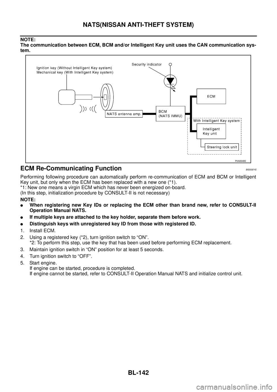
The immobilizer function of the NATS consists of the following:
�Ignition key (models without Intelligent Key system)
�Mechanical key (models with Intelligent Key system)
�NATS antenna amp.
�Steering lock unit. (models with Intelligent Key system)
�BCM
�Intelligent Key unit (models with Intelligent Key system)
�Engine control module (ECM)
�Security indicator
Security indicator
conditionIgnition keyOperation or condition of ignition key
Ignition switch:
ON positionIgnition switch:
ACC positionIgnition switch:
OFF position
(Key is inserted.)Ignition switch:
OFF position
(Remove key.)
Register key OFF Flashing Flashing Flashing
Ignition key not
registeredON Flashing Flashing Flashing
Page 800 of 3502

BL-142
NATS(NISSAN ANTI-THEFT SYSTEM)
NOTE:
The communication between ECM, BCM and/or Intelligent Key unit uses the CAN communication sys-
tem.
ECM Re-Communicating FunctionBIS000YE
Performing following procedure can automatically perform re-communication of ECM and BCM or Intelligent
Key unit, but only when the ECM has been replaced with a new one (*1).
*1: New one means a virgin ECM which has never been energized on-board.
(In this step, initialization procedure by CONSULT-II is not necessary)
NOTE:
�When registering new Key IDs or replacing the ECM other than brand new, refer to CONSULT-II
Operation Manual NATS.
�If multiple keys are attached to the key holder, separate them before work.
�Distinguish keys with unregistered key ID from those with registered ID.
1. Install ECM.
2. Using a registered key (*2), turn ignition switch to “ON”.
*2: To perform this step, use the key that has been used before performing ECM replacement.
3. Maintain ignition switch in “ON” position for at least 5 seconds.
4. Turn ignition switch to “OFF”.
5. Start engine.
If engine can be started, procedure is completed.
If engine cannot be started, refer to CONSULT-II Operation Manual NATS and initialize control unit.
PIIA6948E
Page 801 of 3502
NATS(NISSAN ANTI-THEFT SYSTEM)
BL-143
C
D
E
F
G
H
J
K
L
MA
B
BL
Wiring Diagram – NATS –BIS000YF
MODELS WITH INTELLIGENT KEY SYSTEM
TIWM1759E
Page 803 of 3502
NATS(NISSAN ANTI-THEFT SYSTEM)
BL-145
C
D
E
F
G
H
J
K
L
MA
B
BL
MODELS WITHOUT INTELLIGENT KEY SYSTEM
TIWM1760E
Page 804 of 3502

BL-146
NATS(NISSAN ANTI-THEFT SYSTEM)
Terminals and Reference Value for Steering Lock Unit/with Intelligent Key Sys-
tem
BIS000YG
Terminals and Reference Value for Intelligent Key Unit/with Intelligent Key Sys-
tem
BIS000YH
Te r -
minalWire
ColorItemSignal
Input/
OutputCondition
Voltage (V)
(Approx.) Ignition
Knob
PositionOperation Or Conditions
1Y/BBattery power sup-
plyInput LOCK — Battery voltage
2L/YSteering lock unit
power supplyInput LOCK — 5
3L/RSteering lock unit
communication sig-
nalInput/
OutputLOCKPress ignition knob with Intelli-
gent Key inside vehicle.
Other than the above 5
4G/YSteering lock unit
ground—ON — 0
PIIB8449J
Te r -
minalWire
ColorItemSignal
Input/
OutputCondition
Voltage (V)
(Approx.) Ignition
Knob
PositionOperation Or Conditions
1L/YSteering lock unit
power supplyOutput LOCK — 5
2 L CAN communication HInput/
Output—— —
3 P CAN communication LInput/
Output—— —
6 G Ignition power supply Input ON — Battery voltage
7 B/R Key switch Input LOCKInsert mechanical key into
ignition key cylinder.Battery voltage
Remove mechanical key from
ignition key cylinder.0
11 Y/B Battery power supply Input LOCK — Battery voltage
12 B Ground — ON — 0
27 BR Ignition knob switch Input —Press ignition knob. Battery voltage
Return ignition knob to LOCK
position.0
31 G/YSteering lock unit
ground—ON — 0
32 L/RSteering lock unit com-
munication signalInput/
OutputLOCKPress ignition knob with Intelli-
gent Key inside vehicle.
Other than the above 5
PIIB8449J
Page 805 of 3502

NATS(NISSAN ANTI-THEFT SYSTEM)
BL-147
C
D
E
F
G
H
J
K
L
MA
B
BL
Terminals and Reference Value for BCMBIS000YI
*: With Intelligent Key systemTe r -
minalWire
ColorItemSignal
Input/
OutputCondition
Voltage (V)
(Approx.) Ignition
Knob
PositionOperation Or Conditions
21 P/L NATS antenna amp. Output — Ignition knob OFF → ON positionShould move just after
turning ignition knob
“ON” pointer tester
23 L/B Security indicator lamp Output LOCKGoes OFF → illuminates (Every 2.4
seconds)Battery voltage → 0
25 LG NATS antenna amp.Input/
Output— Ignition knob OFF → ON positionShould move just after
turning ignition knob
“ON” pointer tester
37* B/R Key switch Input —Insert mechanical key into ignition key
cylinderBattery voltage
Remove mechanical key from ignition
key cylinder0
38 R Ignition power supply Input ON Ignition knob ON or START position Battery voltage
39 L CAN-HInput/
Output—— —
40 P CAN-LInput/
Output—— —
42 Y/R Battery power supply Input LOCK — Battery voltage
52 B Ground — ON — 0
55 W/B Battery power supply Input LOCK — Battery voltage
Page 807 of 3502

NATS(NISSAN ANTI-THEFT SYSTEM)
BL-149
C
D
E
F
G
H
J
K
L
MA
B
BL
8. Perform each diagnostic test mode according to each service
procedure.
For further information, see the CONSULT-II Operation Manual,
NATS.
CONSULT-II DIAGNOSTIC TEST MODE FUNCTION
NOTE:
When any initialization is performed, all ID numbers previously registered will be erased and all ignition key or
mechanical key must be registered again. The engine cannot be started with an unregistered key. The system
will show “DIFFERENCE OF KEY” or “LOCK MODE” as a self-diagnostic result on the CONSULT-II screen.
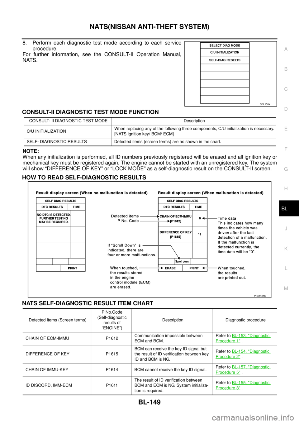
HOW TO READ SELF-DIAGNOSTIC RESULTS
NATS SELF-DIAGNOSTIC RESULT ITEM CHART
SEL150X
CONSULT- II DIAGNOSTIC TEST MODE Description
C/U INITIALIZATIONWhen replacing any of the following three components, C/U initialization is necessary.
[NATS ignition key/ BCM/ ECM]
SELF- DIAGNOSTIC RESULTS Detected items (screen terms) are as shown in the chart.
PIIA1124E
Detected items (Screen terms)P No.Code
(Self-diagnostic
results of
“ENGINE”)Description Diagnostic procedure
CHAIN OF ECM-IMMU P1612Communication impossible between
ECM and BCM.Refer to BL-153, "
Diagnostic
Procedure 1" .
DIFFERENCE OF KEY P1615BCM can receive the key ID signal but
the result of ID verification between key
ID and BCM is NG.Refer to BL-154, "
Diagnostic
Procedure 2" .
CHAIN OF IMMU-KEY P1614 BCM cannot receive the key ID signal.Refer to BL-157, "
Diagnostic
Procedure 5" .
ID DISCORD, IMM-ECM P1611The result of ID verification between
BCM and ECM is NG. System initializa-
tion is required.Refer to BL-155, "
Diagnostic
Procedure 3" .
Page 808 of 3502
BL-150
NATS(NISSAN ANTI-THEFT SYSTEM)
LOCK MODE P1610When the starting operation is performed
5 or more times consecutively under the
following conditions, IVIS(NATS) will shift
the mode to one which prevents the
engine from being started.
�unregistered ignition key is used (with-
out intelligent key system)
�BCM or ECM malfunctioningRefer to BL-156, "
Diagnostic
Procedure 4" .
DON'T ERASE BEFORE
CHECKING ENG DIAG—Engine trouble data and NATS trouble
data have been detected in ECM.Refer to BL-151, "
WORK
FLOW" . Detected items (Screen terms)P No.Code
(Self-diagnostic
results of
“ENGINE”)Description Diagnostic procedure