Page 776 of 3502
BL-118
INTELLIGENT KEY SYSTEM
INTELLIGENT KEY BATTERY INSPECTION
Check by connecting a resistance (approximately 300Ω) so that the
current value becomes about 10 mA.
Standard : Approx. 2.5 - 3.0V
OCC0607D
Page 781 of 3502
FRONT DOOR LOCK
BL-123
C
D
E
F
G
H
J
K
L
MA
B
BL
FRONT DOOR LOCKPFP:80502
Component StructureBIS000XV
Removal and Installation BIS000XW
REMOVAL
1. Remove the front door finisher. Refer to EI-35, "DOOR FINISHER" .
2. Disconnect inside handle cable and lock knob cable from inside handle.
CAUTION:
During removal and installation, work so as not to bend the
ends of the lock knob cable and inside handle cable.
1. Outside handle 2. Front gasket 3. TORX bolt (T30)
4. Lock knob cable 5. Inside handle 6. Screw
7. Inside handle cable 8. Door lock assembly 9. Outside handle cable
10. Clip 11. Key cylinder connecting rod (Driver
side only)12. TORX bolt (T30)
13. Outside handle bracket 14. TORX bolt (T30) 15. Grommet
16. Rear gasket 17. Door key cylinder assembly (Driver
side)
PIIB0282E
PIIA0632E
Page 782 of 3502
BL-124
FRONT DOOR LOCK
3. Remove the front door glass and front door module assembly. Refer to GW-46, "FRONT DOOR GLASS
AND REGULATOR" .
4. Remove key cylinder connecting rod (key cylinder side). (Driver side only)
5. Disconnect door antenna and door request switch connector
and remove harness clamp. (Models with intelligent key systems
only)
6. Remove door side grommet, and remove door key cylinder assembly (driver side) and outside handle
escutcheon (passenger side) bolts (TORX T30) from grommet hole.
CAUTION:
Do not forcibly remove the TORX bolts (T30).
7. Reach to separate the key cylinder rod connection (on the handle).
8. While pulling the outside handle, remove door key cylinder
assembly (driver side) and outside handle escutcheon (passen-
ger side).
9. While pulling outside handle, slide toward rear of vehicle to
remove outside handle.
10. Remove the front gasket and rear gasket.
PIIB0283E
MIIB0128E
MIIB0129E
MIIB0130E
Page 784 of 3502
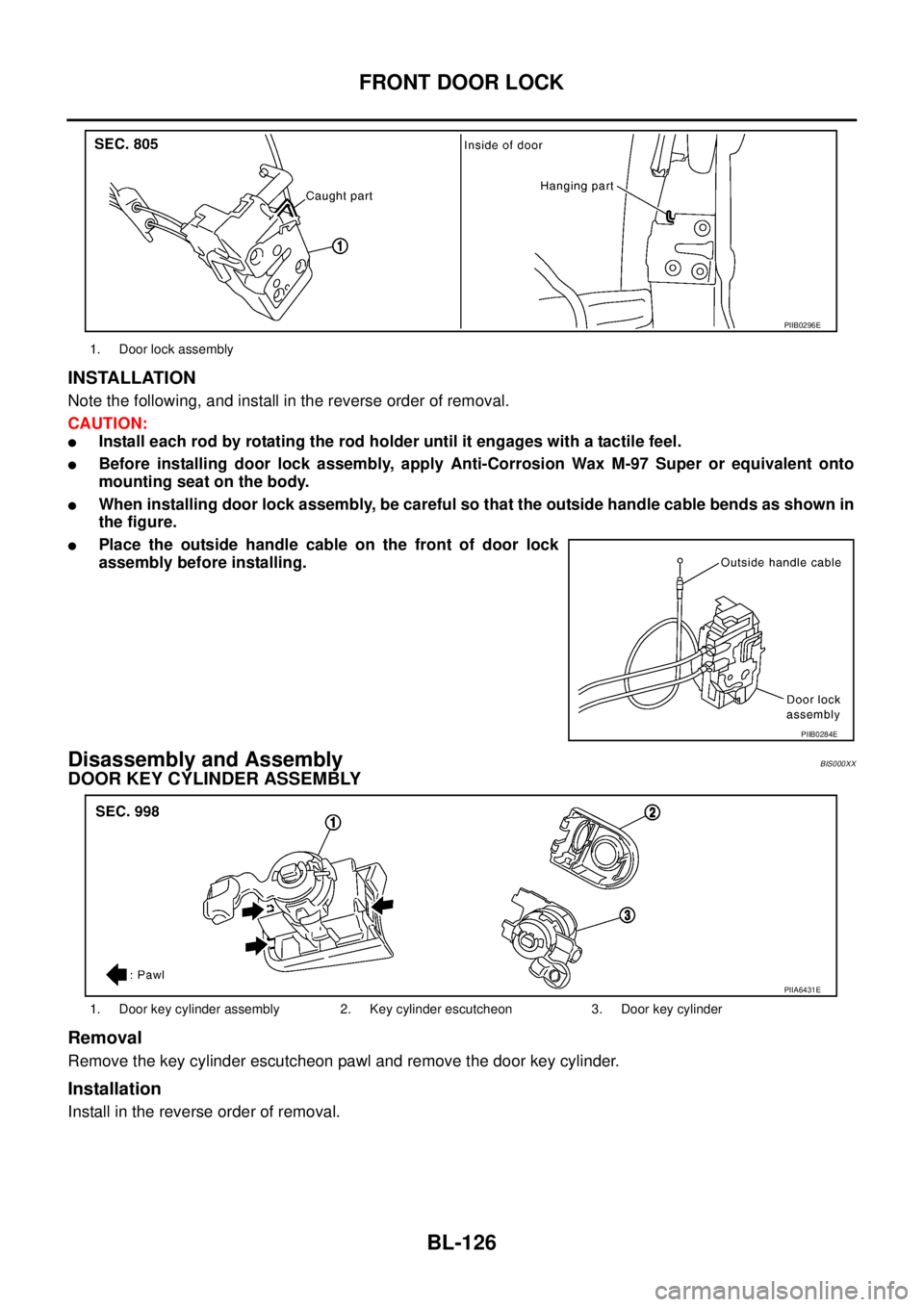
BL-126
FRONT DOOR LOCK
INSTALLATION
Note the following, and install in the reverse order of removal.
CAUTION:
�Install each rod by rotating the rod holder until it engages with a tactile feel.
�Before installing door lock assembly, apply Anti-Corrosion Wax M-97 Super or equivalent onto
mounting seat on the body.
�When installing door lock assembly, be careful so that the outside handle cable bends as shown in
the figure.
�Place the outside handle cable on the front of door lock
assembly before installing.
Disassembly and AssemblyBIS000XX
DOOR KEY CYLINDER ASSEMBLY
Removal
Remove the key cylinder escutcheon pawl and remove the door key cylinder.
Installation
Install in the reverse order of removal.
1. Door lock assembly
PIIB0296E
PIIB0284E
1. Door key cylinder assembly 2. Key cylinder escutcheon 3. Door key cylinder
PIIA6431E
Page 785 of 3502
FRONT DOOR LOCK
BL-127
C
D
E
F
G
H
J
K
L
MA
B
BL
OUTSIDE HANDLE
Removal
1. Remove handle cover screws.
2. Remove handle cover, and then remove door antenna. (Vehicles with intelligent key systems only)
Installation
Install in the reverse order of removal.
1. Outside handle 2. Screw 3. Handle cover
4. Door request switch 5. Pawl 6. Door antenna
PIIB0285E
Page 794 of 3502

BL-136
TRUNK LID OPENER
TRUNK LID OPENERPFP:84640
Component Parts and Harness Connector LocationBIS000Y6
System DescriptionBIS000Y7
Power is supplied at all times
�through 50A fusible link (letter M, located in fuse and fusible link box)
�to BCM terminal 55,
�through 15A fuse [No.17, located in fuse block (J/B)]
�to BCM terminal 42.
Ground is supplied
�to BCM terminals 52
�through body grounds M71 and M72.
When trunk lid opener switch is ON (pushed), ground is supplied
�to BCM terminal 30
�through trunk lid opener switch terminals 3 and 2, and
�through body grounds M71 and M72.
And power is supplied
�through BCM terminal 68
�to trunk lid opener actuator terminal 2.
Ground is supplied
�to trunk lid opener actuator terminal 1, and
�through body grounds B214 and B217.
Then BCM unlocks trunk lid opener actuator.
TRUNK LID OPENER OPERATION
When trunk lid opener switch or trunk button of key fob is ON, trunk opener actuator unlocked by BCM.
BCM can unlock trunk lid opener actuator when
�vehicle speed is less than 5 km/h (3MPH)
BCM does not unlock trunk lid opener actuator when
�vehicle speed is more than 5 km/h (3MPH)
1. BCM M3,M4,M5 2. Trunk lid opener switch D9 3. Trunk lid lock assembly T7
(Trunk room lamp switch)
PIIB8753E
Page 796 of 3502
BIS000YA
CONSULT-II can display each diagnostic item using the diagnostic test modes shown following.
CO")
BL-138
TRUNK LID OPENER
Terminal and Reference Value for BCMBIS000Y9
CONSULT-II Function (BCM)BIS000YA
CONSULT-II can display each diagnostic item using the diagnostic test modes shown following.
CONSULT-II STRAT PROCEDURE
Refer toGI-34, "CONSULT-II Start Procedure" .
CONSULT-II APPLICATION ITEMS
Data Monitor
*: With Intelligent Key system
Active Test
Te r m i -
nalWire
colorItemSignal
Input/
OutputConditionVoltage(V)
(Approx.)
30 L/O Trunk lid opener switch Input Trunk lid opener switchON 0
OFF Battery voltage
42 Y/R Power source (Fuse) Input — Battery voltage
52 B Ground — — 0
55 W/B Power source (Fusible link) Input — Battery voltage
57 V/W Trunk room lamp switch Input Trunk lidOPEN 0
CLOSE Battery voltage
68 R Trunk lid opener output signal Output Trunk lid opener switchON 0 → Battery voltage → 0
OFF 0
BCM diagnosis
partInspection item, Self-diagnosis
modeContent
Door lockDATA MONITOR Displays BCM input data on real-time basis.
ACTIVE TEST Sends drive signals to trunk lid opener actuator to perform operation check.
Monitor item Content
KEY ON SW Indicates [ON/OFF] condition of key switch.
KYLS TRNK/HAT Indicates [ON/OFF] condition of trunk open signal from key fob.
IKEY TRNK/HAT* Indicates [ON/OFF] condition of trunk open signal from Intelligent Key
TRNK OPNR SW Indicates [ON/OFF] condition of trunk lid open signal from trunk lid opener switch.
VEHICLE SPEED Indicates [km/h] condition of vehicle speed.
Test item Content
TRUNK/GLASS HATCHThis test is able to check trunk lid opener actuators unlock operation.
These actuators lock when “OPEN” on CONSULT-II screen is touched.
Page 798 of 3502

NOTE:
If customer reports a “NO START” condition, request ALL ignition key (without intelligent key system) or
mechanical key (with intelligent key system)")
BL-140
NATS(NISSAN ANTI-THEFT SYSTEM)
NOTE:
If customer reports a “NO START” condition, request ALL ignition key (without intelligent key system) or
mechanical key (with intelligent key system) to be brought to the dealer to check for a NATS malfunction.
System DescriptionBIS000YC
DESCRIPTION
NATS (Nissan Anti-Theft System) has the following immobilizer functions:
�Engine immobilizer shows high anti-theft performance to prevent engine start by other than the owner
(registered key: ignition key, mechanical key and Intelligent Key).
�Only a key with key ID registered in BCM and ECM can start engine, and shows high anti-theft perfor-
mance to prevent key from being copied or stolen.
�In the vehicle without Intelligent Key system, security indicator always flashes with other than ignition
switch ON or START position.
�In the vehicle with Intelligent Key system, security indicator always flashes with mechanical key removed
condition (key switch OFF) and ignition knob released condition on LOCK position (ignition knob switch
OFF).
�Therefore, NATS warns outsiders that the vehicle is equipped with the anti-theft system.
�If system detects malfunction, it turns on security indicator in ignition switch ON position.
�If the owner requires, mechanical key ID can be registered for up to 5 keys.
�During trouble diagnosis or when the following parts have been replaced, and if ignition key or mechanical
key is added, registration* is required.
*: All keys kept by the owner of the vehicle should be registered with ignition key or mechanical key.
–ECM
–BCM
–Ignition key (models without Intelligent Key system)
–Mechanical key (models with Intelligent Key system)
�NATS trouble diagnoses, system initialization and additional registration of other NATS ignition key or
mechanical key IDs must be performed using CONSULT-II hardware and CONSULT-II NATS software.
When NATS initialization has been completed, the ID of the inserted ignition key or mechanical key IDs
can be performed.
Regarding the procedures of NATS initialization and ignition key or mechanical key ID registration, refer to
CONSULT-II Operation Manual, NATS.
 so that the
current value becomes about 10 mA.
Standard : Approx. 2.5 - 3.0V")

. (D")