Page 1273 of 3502
WARNING CHIME
DI-67
C
D
E
F
G
H
I
J
L
MA
B
DI
2. CHECK POWER SUPPLY CIRCUIT
Check voltage between BCM harness connector terminals and
ground.
OK or NG
OK >> GO TO 3.
NG >> Check harness between BCM and fuse or fusible link.
3. CHECK GROUND CIRCUIT
1. Turn ignition switch OFF.
2. Disconnect BCM connector.
3. Check continuity between BCM harness connector M4 terminal
52 and ground.
OK or NG
OK >> INSPECTION END
NG >> Repair harness or connector.
Key Warning Chime and Light Warning Chime Does Not OperatedBKS001T8
1. CHECK CHIME OPERATION
1. Select “BCM” on CONSULT-II.
2. Select “BUZZER” on CONSULT-ll, and then perform “LIGHT
WARN ALM” or “IGN KEY WARN ALM” of “ACTIVE TEST”.
Does chime sound?
YES >> GO TO 3.
NO >> GO TO 2.
Terminals Ignition switch position
(+)
(–) OFF ON
Connector Terminal
M455
GroundBattery voltage Battery voltage
42 Battery voltage Battery voltage
M3 38 0 V Battery voltage
SKIB0785E
52 – Ground : Continuity should exist.
SKIB0226E
SKIA6331E
Page 1275 of 3502
WARNING CHIME
DI-69
C
D
E
F
G
H
I
J
L
MA
B
DI
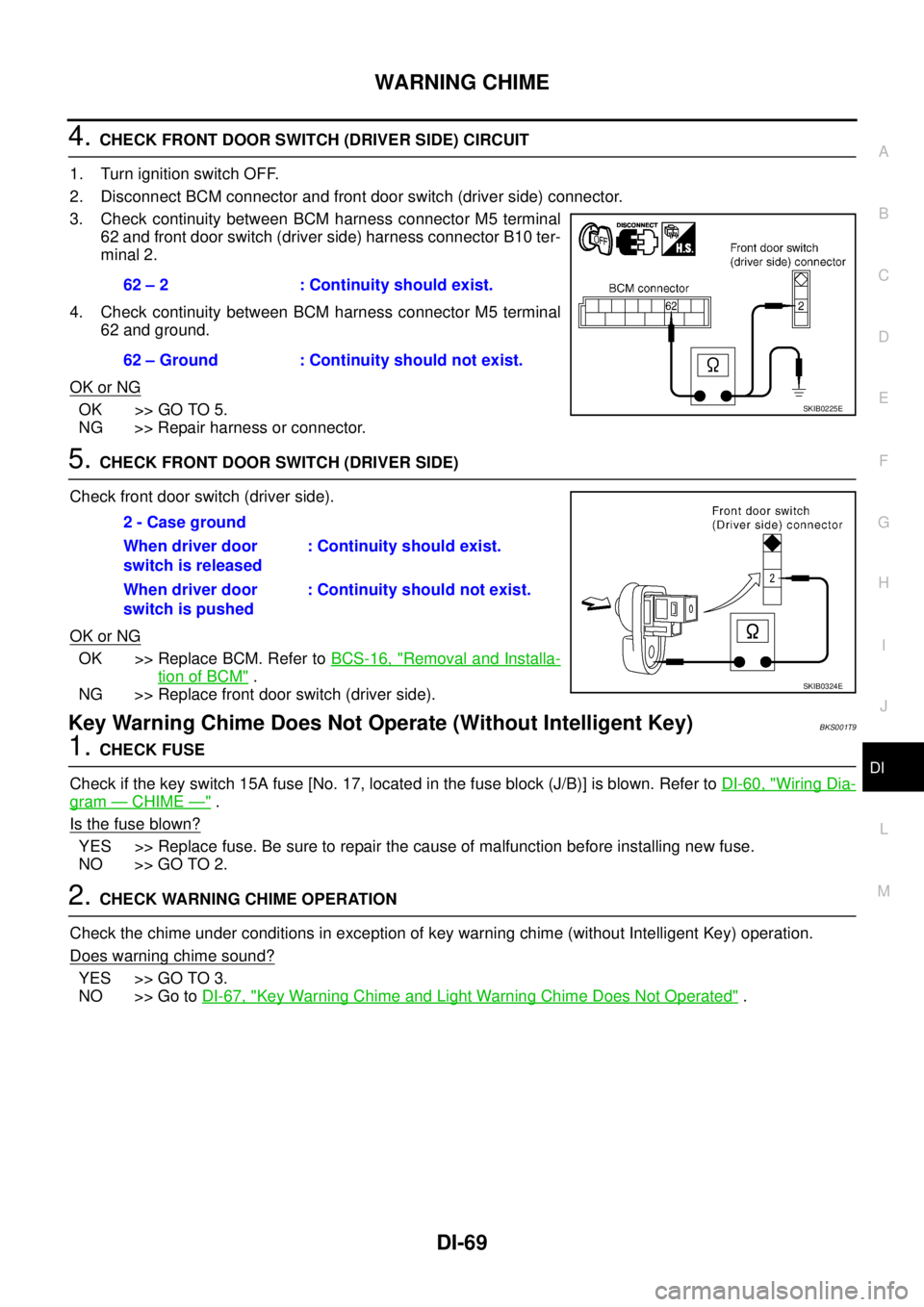
4. CHECK FRONT DOOR SWITCH (DRIVER SIDE) CIRCUIT
1. Turn ignition switch OFF.
2. Disconnect BCM connector and front door switch (driver side) connector.
3. Check continuity between BCM harness connector M5 terminal
62 and front door switch (driver side) harness connector B10 ter-
minal 2.
4. Check continuity between BCM harness connector M5 terminal
62 and ground.
OK or NG
OK >> GO TO 5.
NG >> Repair harness or connector.
5. CHECK FRONT DOOR SWITCH (DRIVER SIDE)
Check front door switch (driver side).
OK or NG
OK >> Replace BCM. Refer to BCS-16, "Removal and Installa-
tion of BCM" .
NG >> Replace front door switch (driver side).
Key Warning Chime Does Not Operate (Without Intelligent Key)BKS001T9
1. CHECK FUSE
Check if the key switch 15A fuse [No. 17, located in the fuse block (J/B)] is blown. Refer to DI-60, "
Wiring Dia-
gram — CHIME —" .
Is the fuse blown?
YES >> Replace fuse. Be sure to repair the cause of malfunction before installing new fuse.
NO >> GO TO 2.
2. CHECK WARNING CHIME OPERATION
Check the chime under conditions in exception of key warning chime (without Intelligent Key) operation.
Does warning chime sound?
YES >> GO TO 3.
NO >> Go to DI-67, "
Key Warning Chime and Light Warning Chime Does Not Operated" . 62 – 2 : Continuity should exist.
62 – Ground : Continuity should not exist.
SKIB0225E
2 - Case ground
When driver door
switch is released: Continuity should exist.
When driver door
switch is pushed: Continuity should not exist.
SKIB0324E
Page 1276 of 3502
DI-70
WARNING CHIME
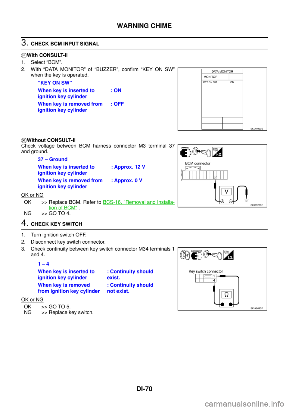
3. CHECK BCM INPUT SIGNAL
With CONSULT-ll
1. Select “BCM”.
2. With “DATA MONITOR” of “BUZZER”, confirm “KEY ON SW”
when the key is operated.
Without CONSULT-ll
Check voltage between BCM harness connector M3 terminal 37
and ground.
OK or NG
OK >> Replace BCM. Refer to BCS-16, "Removal and Installa-
tion of BCM" .
NG >> GO TO 4.
4. CHECK KEY SWITCH
1. Turn ignition switch OFF.
2. Disconnect key switch connector.
3. Check continuity between key switch connector M34 terminals 1
and 4.
OK or NG
OK >> GO TO 5.
NG >> Replace key switch.“KEY ON SW”
When key is inserted to
ignition key cylinder: ON
When key is removed from
ignition key cylinder: OFF
SKIA1960E
37 – Ground
When key is inserted to
ignition key cylinder: Approx. 12 V
When key is removed from
ignition key cylinder: Approx. 0 V
SKIB0280E
1 – 4
When key is inserted to
ignition key cylinder: Continuity should
exist.
When key is removed
from ignition key cylinder: Continuity should
not exist.
SKIA8695E
Page 1277 of 3502
WARNING CHIME
DI-71
C
D
E
F
G
H
I
J
L
MA
B
DI
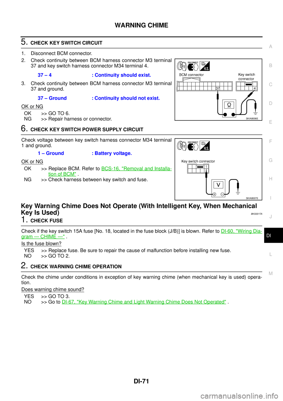
5. CHECK KEY SWITCH CIRCUIT
1. Disconnect BCM connector.
2. Check continuity between BCM harness connector M3 terminal
37 and key switch harness connector M34 terminal 4.
3. Check continuity between BCM harness connector M3 terminal
37 and ground.
OK or NG
OK >> GO TO 6.
NG >> Repair harness or connector.
6. CHECK KEY SWITCH POWER SUPPLY CIRCUIT
Check voltage between key switch harness connector M34 terminal
1 and ground.
OK or NG
OK >> Replace BCM. Refer to BCS-16, "Removal and Installa-
tion of BCM" .
NG >> Check harness between key switch and fuse.
Key Warning Chime Does Not Operate (With Intelligent Key, When Mechanical
Key Is Used)
BKS001TA
1. CHECK FUSE
Check if the key switch 15A fuse [No. 18, located in the fuse block (J/B)] is blown. Refer to DI-60, "
Wiring Dia-
gram — CHIME —" .
Is the fuse blown?
YES >> Replace fuse. Be sure to repair the cause of malfunction before installing new fuse.
NO >> GO TO 2.
2. CHECK WARNING CHIME OPERATION
Check the chime under conditions in exception of key warning chime (when mechanical key is used) opera-
tion.
Does warning chime sound?
YES >> GO TO 3.
NO >> Go to DI-67, "
Key Warning Chime and Light Warning Chime Does Not Operated" . 37 – 4 : Continuity should exist.
37 – Ground : Continuity should not exist.
SKIA8696E
1 – Ground : Battery voltage.
SKIA8697E
Page 1278 of 3502
DI-72
WARNING CHIME
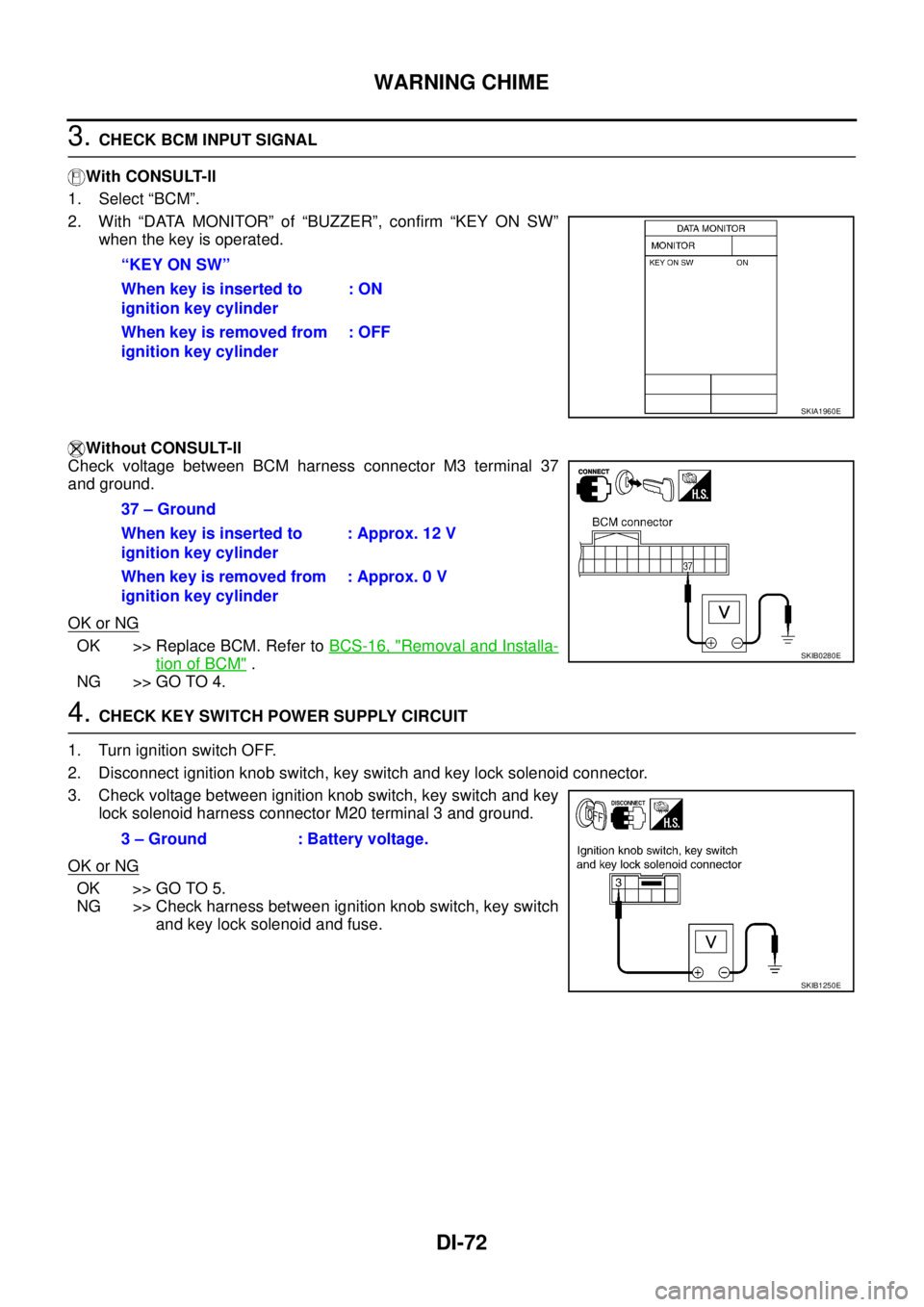
3. CHECK BCM INPUT SIGNAL
With CONSULT-ll
1. Select “BCM”.
2. With “DATA MONITOR” of “BUZZER”, confirm “KEY ON SW”
when the key is operated.
Without CONSULT-ll
Check voltage between BCM harness connector M3 terminal 37
and ground.
OK or NG
OK >> Replace BCM. Refer to BCS-16, "Removal and Installa-
tion of BCM" .
NG >> GO TO 4.
4. CHECK KEY SWITCH POWER SUPPLY CIRCUIT
1. Turn ignition switch OFF.
2. Disconnect ignition knob switch, key switch and key lock solenoid connector.
3. Check voltage between ignition knob switch, key switch and key
lock solenoid harness connector M20 terminal 3 and ground.
OK or NG
OK >> GO TO 5.
NG >> Check harness between ignition knob switch, key switch
and key lock solenoid and fuse. “KEY ON SW”
When key is inserted to
ignition key cylinder: ON
When key is removed from
ignition key cylinder: OFF
SKIA1960E
37 – Ground
When key is inserted to
ignition key cylinder: Approx. 12 V
When key is removed from
ignition key cylinder: Approx. 0 V
SKIB0280E
3 – Ground : Battery voltage.
SKIB1250E
Page 1279 of 3502
WARNING CHIME
DI-73
C
D
E
F
G
H
I
J
L
MA
B
DI
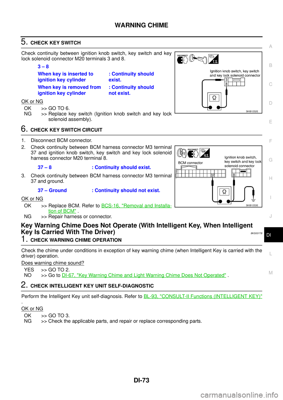
5. CHECK KEY SWITCH
Check continuity between ignition knob switch, key switch and key
lock solenoid connector M20 terminals 3 and 8.
OK or NG
OK >> GO TO 6.
NG >> Replace key switch (Ignition knob switch and key lock
solenoid assembly).
6. CHECK KEY SWITCH CIRCUIT
1. Disconnect BCM connector.
2. Check continuity between BCM harness connector M3 terminal
37 and ignition knob switch, key switch and key lock solenoid
harness connector M20 terminal 8.
3. Check continuity between BCM harness connector M3 terminal
37 and ground.
OK or NG
OK >> Replace BCM. Refer to BCS-16, "Removal and Installa-
tion of BCM" .
NG >> Repair harness or connector.
Key Warning Chime Does Not Operate (With Intelligent Key, When Intelligent
Key Is Carried With The Driver)
BKS001TB
1. CHECK WARNING CHIME OPERATION
Check the chime under conditions in exception of key warning chime (when Intelligent Key is carried with the
driver) operation.
Does warning chime sound?
YES >> GO TO 2.
NO >> Go to DI-67, "
Key Warning Chime and Light Warning Chime Does Not Operated" .
2. CHECK INTELLIGENT KEY UNIT SELF-DIAGNOSTIC
Perform the Intelligent Key unit self-diagnosis. Refer to BL-93, "
CONSULT-II Functions (INTELLIGENT KEY)"
.
OK or NG
OK >> GO TO 3.
NG >> Check the applicable parts, and repair or replace corresponding parts.3 – 8
When key is inserted to
ignition key cylinder: Continuity should
exist.
When key is removed from
ignition key cylinder: Continuity should
not exist.
SKIB1252E
37 – 8 : Continuity should exist.
37 – Ground : Continuity should not exist.
SKIB1253E
Page 1280 of 3502
DI-74
WARNING CHIME
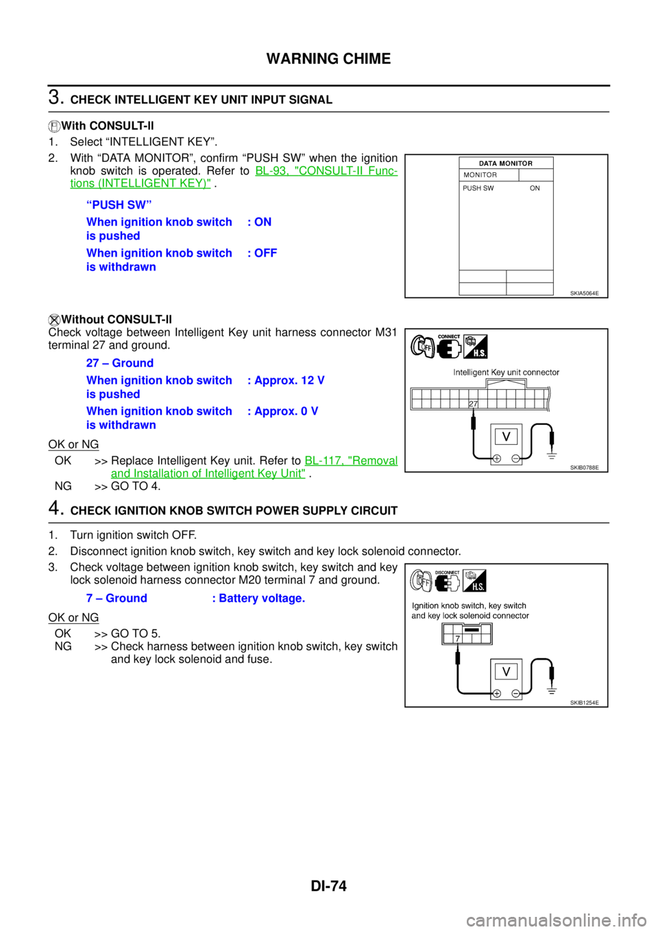
3. CHECK INTELLIGENT KEY UNIT INPUT SIGNAL
With CONSULT-ll
1. Select “INTELLIGENT KEY”.
2. With “DATA MONITOR”, confirm “PUSH SW” when the ignition
knob switch is operated. Refer to BL-93, "
CONSULT-II Func-
tions (INTELLIGENT KEY)" .
Without CONSULT-ll
Check voltage between Intelligent Key unit harness connector M31
terminal 27 and ground.
OK or NG
OK >> Replace Intelligent Key unit. Refer to BL-117, "Removal
and Installation of Intelligent Key Unit" .
NG >> GO TO 4.
4. CHECK IGNITION KNOB SWITCH POWER SUPPLY CIRCUIT
1. Turn ignition switch OFF.
2. Disconnect ignition knob switch, key switch and key lock solenoid connector.
3. Check voltage between ignition knob switch, key switch and key
lock solenoid harness connector M20 terminal 7 and ground.
OK or NG
OK >> GO TO 5.
NG >> Check harness between ignition knob switch, key switch
and key lock solenoid and fuse. “PUSH SW”
When ignition knob switch
is pushed: ON
When ignition knob switch
is withdrawn: OFF
SKIA5064E
27 – Ground
When ignition knob switch
is pushed: Approx. 12 V
When ignition knob switch
is withdrawn: Approx. 0 V
SKIB0788E
7 – Ground : Battery voltage.
SKIB1254E
Page 1281 of 3502
WARNING CHIME
DI-75
C
D
E
F
G
H
I
J
L
MA
B
DI
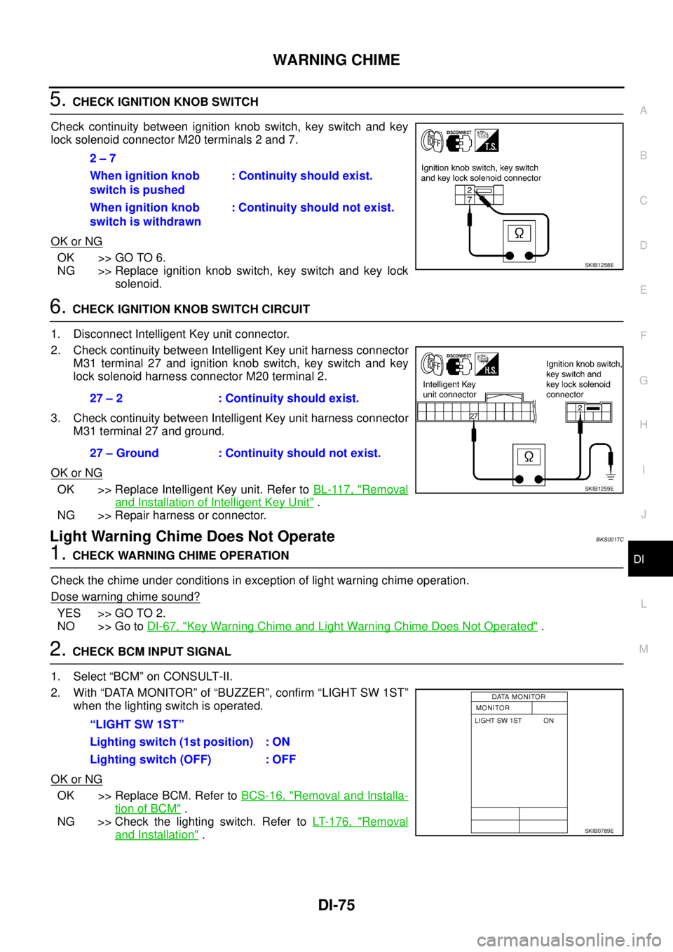
5. CHECK IGNITION KNOB SWITCH
Check continuity between ignition knob switch, key switch and key
lock solenoid connector M20 terminals 2 and 7.
OK or NG
OK >> GO TO 6.
NG >> Replace ignition knob switch, key switch and key lock
solenoid.
6. CHECK IGNITION KNOB SWITCH CIRCUIT
1. Disconnect Intelligent Key unit connector.
2. Check continuity between Intelligent Key unit harness connector
M31 terminal 27 and ignition knob switch, key switch and key
lock solenoid harness connector M20 terminal 2.
3. Check continuity between Intelligent Key unit harness connector
M31 terminal 27 and ground.
OK or NG
OK >> Replace Intelligent Key unit. Refer to BL-117, "Removal
and Installation of Intelligent Key Unit" .
NG >> Repair harness or connector.
Light Warning Chime Does Not OperateBKS001TC
1. CHECK WARNING CHIME OPERATION
Check the chime under conditions in exception of light warning chime operation.
Dose warning chime sound?
YES >> GO TO 2.
NO >> Go to DI-67, "
Key Warning Chime and Light Warning Chime Does Not Operated" .
2. CHECK BCM INPUT SIGNAL
1. Select “BCM” on CONSULT-II.
2. With “DATA MONITOR” of “BUZZER”, confirm “LIGHT SW 1ST”
when the lighting switch is operated.
OK or NG
OK >> Replace BCM. Refer to BCS-16, "Removal and Installa-
tion of BCM" .
NG >> Check the lighting switch. Refer to LT- 1 7 6 , "
Removal
and Installation" . 2 – 7
When ignition knob
switch is pushed: Continuity should exist.
When ignition knob
switch is withdrawn: Continuity should not exist.
SKIB1258E
27 – 2 : Continuity should exist.
27 – Ground : Continuity should not exist.
SKIB1259E
“LIGHT SW 1ST”
Lighting switch (1st position) : ON
Lighting switch (OFF) : OFF
SKIB0789E