Page 2802 of 3502
LT-114
HEADLAMP AIMING CONTROL (AUTO)
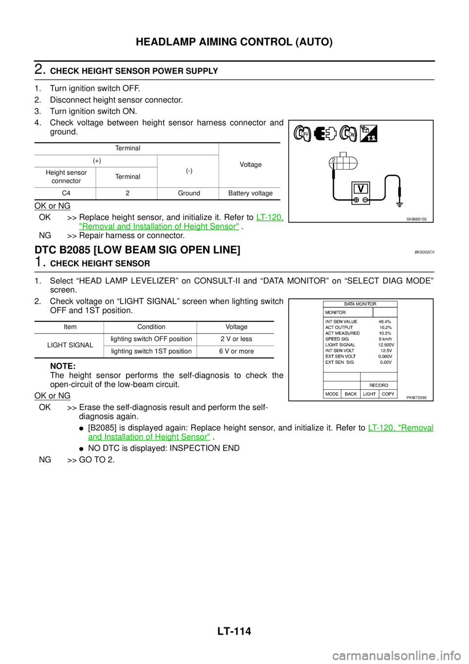
2. CHECK HEIGHT SENSOR POWER SUPPLY
1. Turn ignition switch OFF.
2. Disconnect height sensor connector.
3. Turn ignition switch ON.
4. Check voltage between height sensor harness connector and
ground.
OK or NG
OK >> Replace height sensor, and initialize it. Refer to LT- 1 2 0 ,
"Removal and Installation of Height Sensor" .
NG >> Repair harness or connector.
DTC B2085 [LOW BEAM SIG OPEN LINE]BKS002CV
1. CHECK HEIGHT SENSOR
1. Select “HEAD LAMP LEVELIZER” on CONSULT-II and “DATA MONITOR” on “SELECT DIAG MODE”
screen.
2. Check voltage on “LIGHT SIGNAL” screen when lighting switch
OFF and 1ST position.
NOTE:
The height sensor performs the self-diagnosis to check the
open-circuit of the low-beam circuit.
OK or NG
OK >> Erase the self-diagnosis result and perform the self-
diagnosis again.
�[B2085] is displayed again: Replace height sensor, and initialize it. Refer to LT- 1 2 0 , "Removal
and Installation of Height Sensor" .
�NO DTC is displayed: INSPECTION END
NG >> GO TO 2.
Te r m i n a l
Voltag e (+)
(-)
Height sensor
connectorTe r m i n a l
C4 2 Ground Battery voltage
SKIB8815E
Item Condition Voltage
LIGHT SIGNALlighting switch OFF position 2 V or less
lighting switch 1ST position 6 V or more
PKIB7209E
Page 2803 of 3502
HEADLAMP AIMING CONTROL (AUTO)
LT-115
C
D
E
F
G
H
I
J
L
MA
B
LT
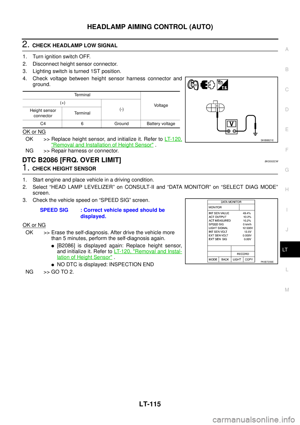
2. CHECK HEADLAMP LOW SIGNAL
1. Turn ignition switch OFF.
2. Disconnect height sensor connector.
3. Lighting switch is turned 1ST position.
4. Check voltage between height sensor harness connector and
ground.
OK or NG
OK >> Replace height sensor, and initialize it. Refer to LT- 1 2 0 ,
"Removal and Installation of Height Sensor" .
NG >> Repair harness or connector.
DTC B2086 [FRQ. OVER LIMIT]BKS002CW
1. CHECK HEIGHT SENSOR
1. Start engine and place vehicle in a driving condition.
2. Select “HEAD LAMP LEVELIZER” on CONSULT-II and “DATA MONITOR” on “SELECT DIAG MODE”
screen.
3. Check the vehicle speed on “SPEED SIG” screen.
OK or NG
OK >> Erase the self-diagnosis. After drive the vehicle more
than 5 minutes, perform the self-diagnosis again.
�[B2086] is displayed again: Replace height sensor,
and initialize it. Refer to LT- 1 2 0 , "
Removal and Instal-
lation of Height Sensor" .
�NO DTC is displayed: INSPECTION END
NG >> GO TO 2.
Terminal
Voltage (+)
(-)
Height sensor
connectorTerminal
C4 6 Ground Battery voltage
SKIB8821E
SPEED SIG : Correct vehicle speed should be
displayed.
PKIB7209E
Page 2804 of 3502
LT-116
HEADLAMP AIMING CONTROL (AUTO)
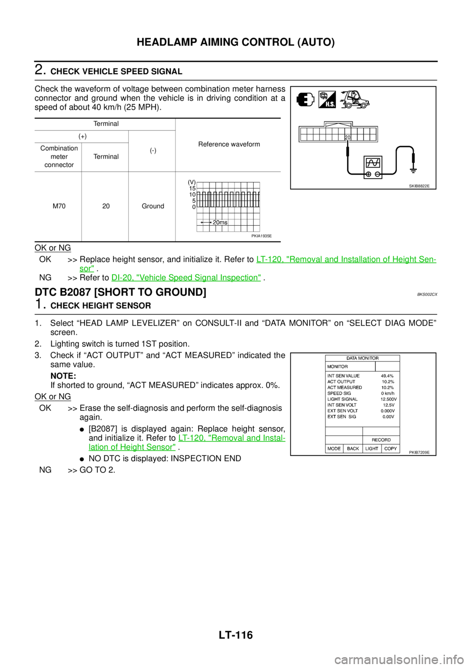
2. CHECK VEHICLE SPEED SIGNAL
Check the waveform of voltage between combination meter harness
connector and ground when the vehicle is in driving condition at a
speed of about 40 km/h (25 MPH).
OK or NG
OK >> Replace height sensor, and initialize it. Refer to LT- 1 2 0 , "Removal and Installation of Height Sen-
sor" .
NG >> Refer to DI-20, "
Vehicle Speed Signal Inspection" .
DTC B2087 [SHORT TO GROUND]BKS002CX
1. CHECK HEIGHT SENSOR
1. Select “HEAD LAMP LEVELIZER” on CONSULT-II and “DATA MONITOR” on “SELECT DIAG MODE”
screen.
2. Lighting switch is turned 1ST position.
3. Check if “ACT OUTPUT” and “ACT MEASURED” indicated the
same value.
NOTE:
If shorted to ground, “ACT MEASURED” indicates approx. 0%.
OK or NG
OK >> Erase the self-diagnosis and perform the self-diagnosis
again.
�[B2087] is displayed again: Replace height sensor,
and initialize it. Refer to LT-120, "
Removal and Instal-
lation of Height Sensor" .
�NO DTC is displayed: INSPECTION END
NG >> GO TO 2.
Terminal
Reference waveform (+)
(-) Combination
meter
connectorTerminal
M70 20 Ground
SKIB8822E
PKIA1935E
PKIB7209E
Page 2805 of 3502
HEADLAMP AIMING CONTROL (AUTO)
LT-117
C
D
E
F
G
H
I
J
L
MA
B
LT
2. CHECK HEADLAMP LEVELIZER
1. Turn ignition switch OFF.
2. Disconnect front combination lamp (RH and LH) connectors.
3. Select “HEAD LAMP LEVELIZER” on CONSULT-II and “DATA MONITOR” on “SELECT DIAG MODE”
screen.
4. Check if “ACT OUTPUT” and “ACT MEASURED” indicated the
same value.
OK or NG
OK >> GO TO 4.
NG >> GO TO 3.
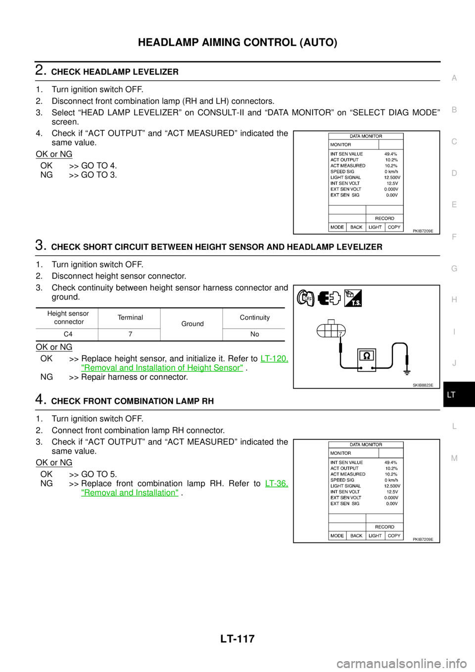
3. CHECK SHORT CIRCUIT BETWEEN HEIGHT SENSOR AND HEADLAMP LEVELIZER
1. Turn ignition switch OFF.
2. Disconnect height sensor connector.
3. Check continuity between height sensor harness connector and
ground.
OK or NG
OK >> Replace height sensor, and initialize it. Refer to LT- 1 2 0 ,
"Removal and Installation of Height Sensor" .
NG >> Repair harness or connector.
4. CHECK FRONT COMBINATION LAMP RH
1. Turn ignition switch OFF.
2. Connect front combination lamp RH connector.
3. Check if “ACT OUTPUT” and “ACT MEASURED” indicated the
same value.
OK or NG
OK >> GO TO 5.
NG >> Replace front combination lamp RH. Refer to LT- 3 6 ,
"Removal and Installation" .
PKIB7209E
Height sensor
connectorTerminal
GroundContinuity
C4 7 No
SKIB8823E
PKIB7209E
Page 2806 of 3502
LT-118
HEADLAMP AIMING CONTROL (AUTO)
5. CHECK FRONT COMBINATION LAMP LH
1. Turn ignition switch OFF.
2. Disconnect front combination lamp RH connector.
3. Connect front combination lamp LH connector.
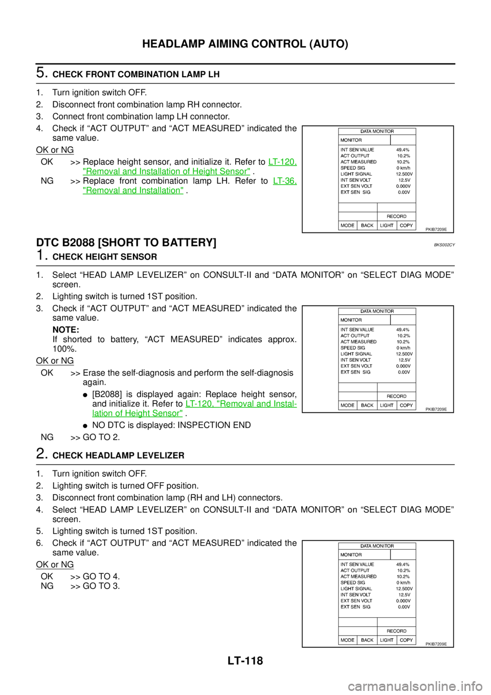
4. Check if “ACT OUTPUT” and “ACT MEASURED” indicated the
same value.
OK or NG
OK >> Replace height sensor, and initialize it. Refer to LT- 1 2 0 ,
"Removal and Installation of Height Sensor" .
NG >> Replace front combination lamp LH. Refer to LT- 3 6 ,
"Removal and Installation" .
DTC B2088 [SHORT TO BATTERY]BKS002CY
1. CHECK HEIGHT SENSOR
1. Select “HEAD LAMP LEVELIZER” on CONSULT-II and “DATA MONITOR” on “SELECT DIAG MODE”
screen.
2. Lighting switch is turned 1ST position.
3. Check if “ACT OUTPUT” and “ACT MEASURED” indicated the
same value.
NOTE:
If shorted to battery, “ACT MEASURED” indicates approx.
100%.
OK or NG
OK >> Erase the self-diagnosis and perform the self-diagnosis
again.
�[B2088] is displayed again: Replace height sensor,
and initialize it. Refer to LT-120, "
Removal and Instal-
lation of Height Sensor" .
�NO DTC is displayed: INSPECTION END
NG >> GO TO 2.
2. CHECK HEADLAMP LEVELIZER
1. Turn ignition switch OFF.
2. Lighting switch is turned OFF position.
3. Disconnect front combination lamp (RH and LH) connectors.
4. Select “HEAD LAMP LEVELIZER” on CONSULT-II and “DATA MONITOR” on “SELECT DIAG MODE”
screen.
5. Lighting switch is turned 1ST position.
6. Check if “ACT OUTPUT” and “ACT MEASURED” indicated the
same value.
OK or NG
OK >> GO TO 4.
NG >> GO TO 3.
PKIB7209E
PKIB7209E
PKIB7209E
Page 2807 of 3502
HEADLAMP AIMING CONTROL (AUTO)
LT-119
C
D
E
F
G
H
I
J
L
MA
B
LT
3. CHECK SHORT CIRCUIT BETWEEN HEIGHT SENSOR AND HEADLAMP LEVELIZER
1. Turn ignition switch OFF.
2. Lighting switch is turned OFF position.
3. Disconnect height sensor connector.
4. Turn ignition switch ON.
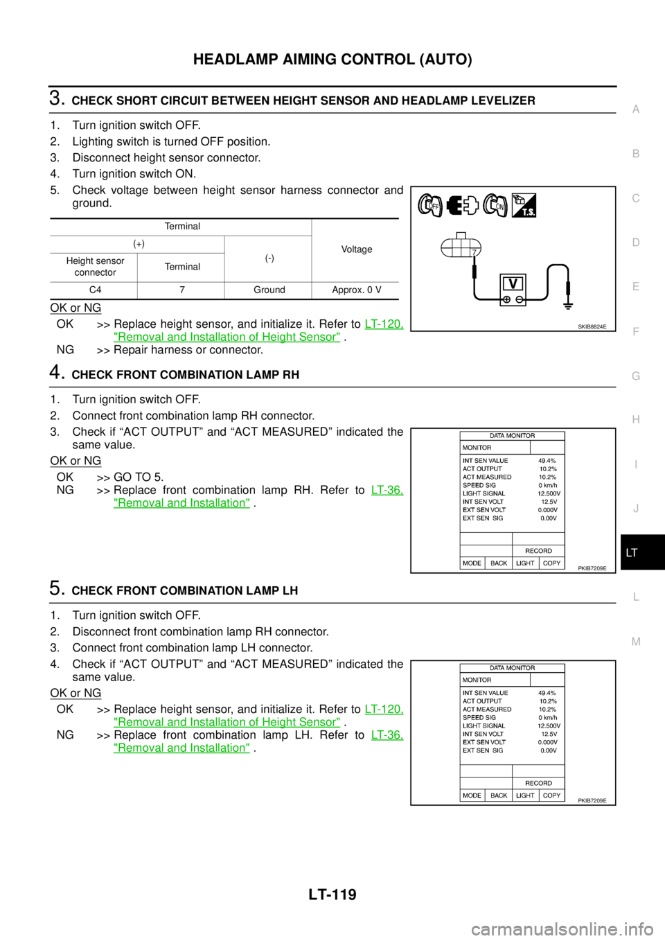
5. Check voltage between height sensor harness connector and
ground.
OK or NG
OK >> Replace height sensor, and initialize it. Refer to LT- 1 2 0 ,
"Removal and Installation of Height Sensor" .
NG >> Repair harness or connector.
4. CHECK FRONT COMBINATION LAMP RH
1. Turn ignition switch OFF.
2. Connect front combination lamp RH connector.
3. Check if “ACT OUTPUT” and “ACT MEASURED” indicated the
same value.
OK or NG
OK >> GO TO 5.
NG >> Replace front combination lamp RH. Refer to LT- 3 6 ,
"Removal and Installation" .
5. CHECK FRONT COMBINATION LAMP LH
1. Turn ignition switch OFF.
2. Disconnect front combination lamp RH connector.
3. Connect front combination lamp LH connector.
4. Check if “ACT OUTPUT” and “ACT MEASURED” indicated the
same value.
OK or NG
OK >> Replace height sensor, and initialize it. Refer to LT- 1 2 0 ,
"Removal and Installation of Height Sensor" .
NG >> Replace front combination lamp LH. Refer to LT- 3 6 ,
"Removal and Installation" .
Terminal
Voltage (+)
(-)
Height sensor
connectorTerminal
C4 7 Ground Approx. 0 V
SKIB8824E
PKIB7209E
PKIB7209E
Page 2808 of 3502
LT-120
HEADLAMP AIMING CONTROL (AUTO)
Removal and Installation of Height SensorBKS002BJ
REMOVAL
1. Turn ignition switch OFF.
2. Disconnect the battery cable from the negative terminal or remove power fuse.
3. Lift-up the vehicle.
4. Disconnect height sensor connector.
5. Remove height sensor linkage mounting nut (A), and remove
height sensor bracket mounting bolts (B).
6. Remove height sensor (1).
INSTALLATION
Installation is the reverse order of removal.
NOTE:
Initialize whenever replacing the height sensor. Refer to LT- 1 0 3 , "
WORK SUPPORT" .
PKIC9223J
Height sensor bracket mounting bolts : 7.0 N·m (0.71 kg-m, 62 ft-lb)
Height sensor linkage mounting nut : 5.5 N·m (0.56 kg-m, 49 ft-lb)
Page 3135 of 3502
POWER STEERING GEAR AND LINKAGE
PS-21
C
D
E
F
H
I
J
K
L
MA
B
PS
DISASSEMBLY
1. Remove cylinder tubes from gear housing assembly.
2. Remove rear cover cap from pinion assembly.
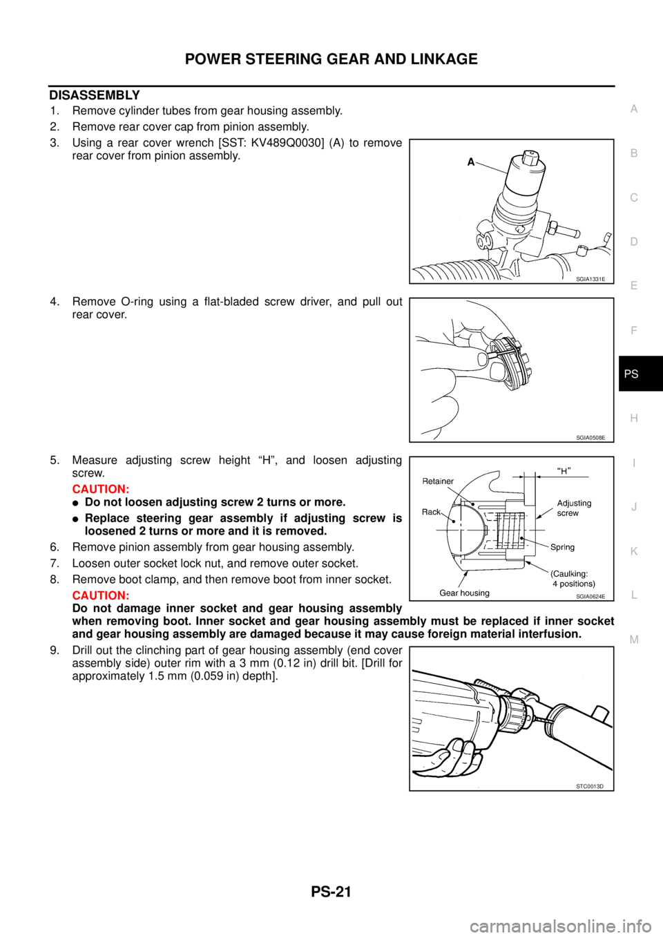
3. Using a rear cover wrench [SST: KV489Q0030] (A) to remove
rear cover from pinion assembly.
4. Remove O-ring using a flat-bladed screw driver, and pull out
rear cover.
5. Measure adjusting screw height “H”, and loosen adjusting
screw.
CAUTION:
�Do not loosen adjusting screw 2 turns or more.
�Replace steering gear assembly if adjusting screw is
loosened 2 turns or more and it is removed.
6. Remove pinion assembly from gear housing assembly.
7. Loosen outer socket lock nut, and remove outer socket.
8. Remove boot clamp, and then remove boot from inner socket.
CAUTION:
Do not damage inner socket and gear housing assembly
when removing boot. Inner socket and gear housing assembly must be replaced if inner socket
and gear housing assembly are damaged because it may cause foreign material interfusion.
9. Drill out the clinching part of gear housing assembly (end cover
assembly side) outer rim with a 3 mm (0.12 in) drill bit. [Drill for
approximately 1.5 mm (0.059 in) depth].
SGIA1331E
SGIA0508E
SGIA0624E
STC0013D