Page 2162 of 3502
![NISSAN TEANA 2003 Service Manual EM-54
[QR]
TIMING CHAIN
REMOVAL
1. Remove the following parts.
�RH front road wheel and tire
�Undercover and splash guard (RH)
�PCV hose; Refer to EM-19, "INTAKE MANIFOLD" .
�Ignition coil; Refer](/manual-img/5/57392/w960_57392-2161.png "NISSAN TEANA 2003 Service Manual EM-54
[QR]
TIMING CHAIN
REMOVAL
1. Remove the following parts.
�RH front road wheel and tire
�Undercover and splash guard (RH)
�PCV hose; Refer to EM-19, \"INTAKE MANIFOLD\" .
�Ignition coil; Refer")
EM-54
[QR]
TIMING CHAIN
REMOVAL
1. Remove the following parts.
�RH front road wheel and tire
�Undercover and splash guard (RH)
�PCV hose; Refer to EM-19, "INTAKE MANIFOLD" .
�Ignition coil; Refer to EM-31, "IGNITION COIL" .
�Rocker cover; Refer to EM-39, "ROCKER COVER" .
�Reservoir tank of radiator; Refer to CO-13, "RADIATOR" .
�Drive belt; Refer to EM-14, "DRIVE BELTS" .
�Alternator; Refer to SC-27, "CHARGING SYSTEM" .
�Drive belt auto-tensioner; Refer to EM-15, "Removal and Installation of Drive Belt Auto-Tensioner" .
�Exhaust front tube; Refer to EX-2, "EXHAUST SYSTEM" .
2. Drain engine oil. Refer to LU-9, "
Changing Engine Oil" .
CAUTION:
Perform this step when engine is cold.
3. Remove A/C compressor with piping connected. Temporarily secure A/C compressor to vehicle side with
a rope to avoid putting a load on them. Refer to ATC-134, "
Removal and Installation of Compressor" .
4. Remove power steering oil pump with piping connected, and secure it to vehicle side temporarily. Refer to
PS-39, "
HYDRAULIC LINE" .
5. Securely support bottom of transaxle with suitable transmission jack.
6. Remove RH engine mounting insulator. Refer to EM-77, "
ENGINE ASSEMBLY" .
7. Remove oil pans (upper and lower), and oil strainer. Refer to EM-26, "
OIL PAN AND OIL STRAINER" .
8. To support engine, temporarily tighten removed front and rear engine mounting through-bolts for removing
oil pans (upper and lower). Refer to EM-77, "
ENGINE ASSEMBLY" .
9. Remove intake valve timing control cover with the following procedure:
a. Disconnect intake valve timing control solenoid valve harness connector.
b. Disconnect ground cables and remove harness clip.
c. Remove intake valve timing control solenoid valve, if necessary.
d. Loosen bolts in reverse order as shown in the figure.
e . U s e s e a l c u t t e r [ S S T: K V 1 0 1111 0 0 ] o r e q u i v a l e n t t o o l t o c u t l i q -
uid gasket for removal.
CAUTION:
Be careful not to damage the mating surfaces.
10. Pull chain guide between camshaft sprockets out through front cover.
11. Set No. 1 cylinder at TDC on its compression stroke with the following procedure:
a. Rotate crankshaft pulley clockwise and align TDC mark to timing
indicator on front cover.
KBIA0085E
KBIA0190E
Page 2163 of 3502
TIMING CHAIN
EM-55
[QR]
C
D
E
F
G
H
I
J
K
L
MA
EM
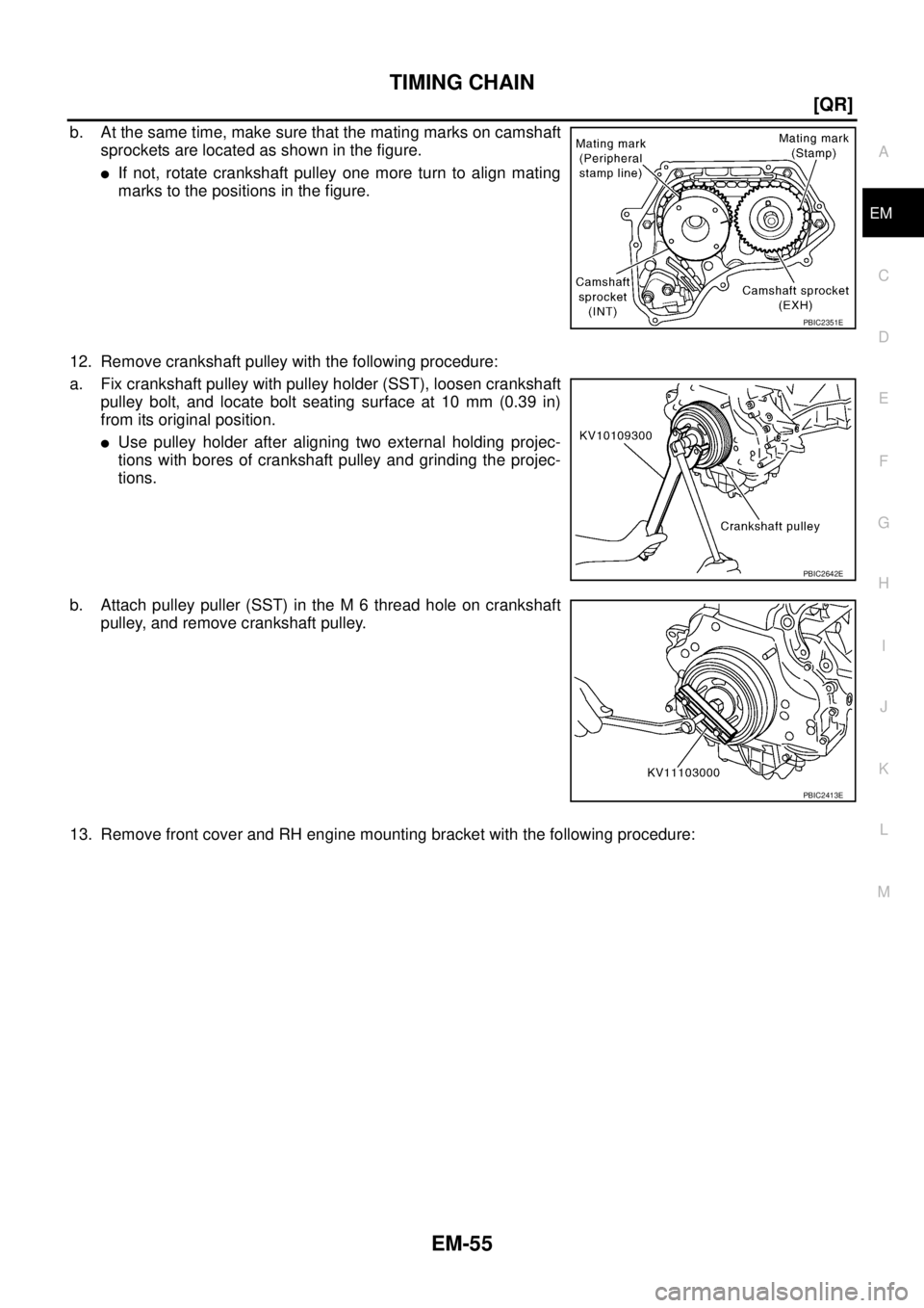
b. At the same time, make sure that the mating marks on camshaft
sprockets are located as shown in the figure.
�If not, rotate crankshaft pulley one more turn to align mating
marks to the positions in the figure.
12. Remove crankshaft pulley with the following procedure:
a. Fix crankshaft pulley with pulley holder (SST), loosen crankshaft
pulley bolt, and locate bolt seating surface at 10 mm (0.39 in)
from its original position.
�Use pulley holder after aligning two external holding projec-
tions with bores of crankshaft pulley and grinding the projec-
tions.
b. Attach pulley puller (SST) in the M 6 thread hole on crankshaft
pulley, and remove crankshaft pulley.
13. Remove front cover and RH engine mounting bracket with the following procedure:
PBIC2351E
PBIC2642E
PBIC2413E
Page 2164 of 3502
![NISSAN TEANA 2003 Service Manual EM-56
[QR]
TIMING CHAIN
a. Loosen mounting bolts in reverse order as shown in the figure,
and remove RH engine mounting bracket.
b . U s e s e a l c u t t e r [ S S T: K V 1 0 1111 0 0 ] o r e](/manual-img/5/57392/w960_57392-2163.png "NISSAN TEANA 2003 Service Manual EM-56
[QR]
TIMING CHAIN
a. Loosen mounting bolts in reverse order as shown in the figure,
and remove RH engine mounting bracket.
b . U s e s e a l c u t t e r [ S S T: K V 1 0 1111 0 0 ] o r e")
EM-56
[QR]
TIMING CHAIN
a. Loosen mounting bolts in reverse order as shown in the figure,
and remove RH engine mounting bracket.
b . U s e s e a l c u t t e r [ S S T: K V 1 0 1111 0 0 ] o r e q u i v a l e n t t o o l t o c u t l i q -
uid gasket for removing front cover.
CAUTION:
Be careful not to damage the mating surfaces.
c. Pull out downward front cover.
CAUTION:
Do not let A/C and power steering pipings interfere with
upper part of front cover.
14. Remove front oil seal from front cover using suitable tool.
CAUTION:
Be careful not to damage front cover.
15. Remove timing chain with the following procedure:
a. Push in chain tensioner plunger. Insert a stopper pin into hole on
chain tensioner body to secure chain tensioner plunger and
remove chain tensioner.
NOTE:
Use approximately 0.5 mm (0.02 in) dia. hard metal pin as a
stopper pin.
b. Remove timing chain.
CAUTION:
Do not rotate crankshaft or camshaft while timing chain is removed. It causes interference
between valve and piston.
16. Remove camshaft sprockets. Refer to EM-41, "
CAMSHAFT" .
17. Remove timing chain slack guide, timing chain tension guide and oil pump drive spacer.
18. Remove balancer unit timing chain tensioner with the following procedure:
a. Lift lever up, and release ratchet claw for return proof.
b. Push tensioner sleeve in, and hold it.
c. Matching the hole on lever with the one on body, insert a stopper
pin to secure tensioner sleeve.
NOTE:
Use approximately 1 mm (0.04 in) dia. hard metal pin as a stop-
per pin.
d. Remove balancer unit timing chain tensioner.
KBIA0083E
KBIA0048E
KBIA0121E
Page 2166 of 3502
![NISSAN TEANA 2003 Service Manual EM-58
[QR]
TIMING CHAIN
INSTALLATION
NOTE:
The figure shows the relationship between the mating mark on each
timing chain and that on the corresponding sprocket, with the com-
ponents installed.
1.](/manual-img/5/57392/w960_57392-2165.png "NISSAN TEANA 2003 Service Manual EM-58
[QR]
TIMING CHAIN
INSTALLATION
NOTE:
The figure shows the relationship between the mating mark on each
timing chain and that on the corresponding sprocket, with the com-
ponents installed.
1.")
EM-58
[QR]
TIMING CHAIN
INSTALLATION
NOTE:
The figure shows the relationship between the mating mark on each
timing chain and that on the corresponding sprocket, with the com-
ponents installed.
1. Make sure that crankshaft key points straight up.
2. Tighten mounting bolts in numerical order as shown in the figure
with the following procedure to install balancer unit.
CAUTION:
If mounting bolts are re-used, check their outer diameter
before installation. Refer to EM-57, "
Balancer Unit Mounting
Bolt Outer Diameter" .
a. Apply new engine oil to threads and seat surfaces of mounting
bolts.
b. Tighten all bolts.
c. Turn all bolts 90 degrees clockwise (angle tightening).
CAUTION:
Check tightening angle with angle wrench (SST) or a pro-
tractor. Do not make judgment by visual check alone.
d. Completely loosen.
CAUTION:
In this step, loosen bolts in reverse order as shown in the
figure.
e. Tighten all bolts.
f. Turn them another 90 degrees clockwise (angle tightening).
PBIC2182E
: 48.1 N·m (4.9 kg-m, 35 ft-lb)KBIA0122E
: 0 N·m (0 kg-m, 0 ft-lb)
: 48.1 N·m (4.9 kg-m, 35 ft-lb)
KBIA0080E
Page 2168 of 3502
![NISSAN TEANA 2003 Service Manual EM-60
[QR]
TIMING CHAIN
b. Apply a continuous bead of liquid gasket with tube presser [SST:
WS39930000] to front cover as shown in the figure.
Use Genuine Liquid Gasket or equivalent.
NOTE:
Applic](/manual-img/5/57392/w960_57392-2167.png "NISSAN TEANA 2003 Service Manual EM-60
[QR]
TIMING CHAIN
b. Apply a continuous bead of liquid gasket with tube presser [SST:
WS39930000] to front cover as shown in the figure.
Use Genuine Liquid Gasket or equivalent.
NOTE:
Applic")
EM-60
[QR]
TIMING CHAIN
b. Apply a continuous bead of liquid gasket with tube presser [SST:
WS39930000] to front cover as shown in the figure.
Use Genuine Liquid Gasket or equivalent.
NOTE:
Application instruction differs depending on the position.
c. Make sure that mating marks of timing chain and each sprocket are still aligned. Then install front cover.
�When installing, align flat faces at oil pump drive spacer and oil pump inner rotor.
CAUTION:
�Do not let A/C and power steering pipings interfere with upper part of front cover.
�Be careful not to damage front oil seal by interference with front end of crankshaft.
d. Tighten mounting bolts in numerical order as shown in the fig-
ure.
�Refer to the following for locating M6 bolts.
�At the same time, install RH engine mounting bracket. (Bolt
positions 1 to 4 in the figure)
e. After all bolts are tightened, retighten them to specified torque in
numerical order as shown in the figure.
CAUTION:
Be sure to wipe off any excessive liquid gasket leaking to
surface for fitting oil pan (upper).
8. Install chain guide between camshaft sprockets.
9. Install intake valve timing control cover with the following procedure:
a. Install oil rings to the camshaft sprocket (INT) insertion points on backside of intake valve timing control
cover.
b. Install O-ring to front cover.Detail of A : Cross over the start of the applica-
tion and the end.
Detail of B : Apply liquid gasket outside of bolt
holes. (For all bolt holes other than
B, apply to the inside.)
Detail of C : Between here only, apply 4.5 - 5.5
mm (0.177 - 0.217 in) dia.
SBIA0267E
Bolt length: Bolt position
45 mm (1.77 in) : 5, 14, 17
20 mm (0.79 in) : Except the above (Except 1 to 4)
KBIA0083E
Page 2169 of 3502
![NISSAN TEANA 2003 Service Manual TIMING CHAIN
EM-61
[QR]
C
D
E
F
G
H
I
J
K
L
MA
EM
c. Apply a continuous bead of liquid gasket with tube presser [SST:
WS39930000] to intake valve timing control cover as shown in
the figure.
Use Gen](/manual-img/5/57392/w960_57392-2168.png "NISSAN TEANA 2003 Service Manual TIMING CHAIN
EM-61
[QR]
C
D
E
F
G
H
I
J
K
L
MA
EM
c. Apply a continuous bead of liquid gasket with tube presser [SST:
WS39930000] to intake valve timing control cover as shown in
the figure.
Use Gen")
TIMING CHAIN
EM-61
[QR]
C
D
E
F
G
H
I
J
K
L
MA
EM
c. Apply a continuous bead of liquid gasket with tube presser [SST:
WS39930000] to intake valve timing control cover as shown in
the figure.
Use Genuine Liquid Gasket or equivalent.
d. Tighten mounting bolts in numerical order as shown in the fig-
ure.
e. Install intake valve timing control solenoid valves to intake valve timing control cover if removed.
f. Connect ground cables, and install harness clip.
10. Insert crankshaft pulley by aligning with crankshaft key.
�When inserting crankshaft pulley with plastic hammer, tap on its center portion (not circumference).
CAUTION:
Install protecting front oil seal lip section from any damage.
11. Tighten crankshaft pulley bolt with the following procedure.
�Secure crankshaft pulley with pulley holder [SST: KV10109300], and tighten crankshaft pulley bolt.
a. Apply new engine oil to thread and seat surfaces of crankshaft pulley bolt.
b. Tighten crankshaft pulley bolt.
c. Put a paint mark on crankshaft pulley, mating with any one of six
easy to recognize angle marks on bolt flange.
d. Turn another 60 degrees clockwise (angle tightening).
�Check the tightening angle with movement of one angle mark.
12. Install all removed parts in the reverse order of removal.
NOTE:
If hydraulic pressure inside timing chain tensioner drops after removal/installation, slack in the guide may
generate a pounding noise during and just after engine start. However, this is normal. Noise will stop after
hydraulic pressure rises.
SBIA0260E
KBIA0085E
: 42.1 N·m (4.3 kg-m, 31 ft-lb)
SEM751G
Page 2170 of 3502
![NISSAN TEANA 2003 Service Manual EM-62
[QR]
OIL SEAL
OIL SEALPFP:12279
Removal and Installation of Valve Oil SealBBS00598
REMOVAL
1. Remove camshafts. Refer to EM-41, "CAMSHAFT" .
2. Remove valve lifters. Refer to EM-41, "
CAMSHAF](/manual-img/5/57392/w960_57392-2169.png "NISSAN TEANA 2003 Service Manual EM-62
[QR]
OIL SEAL
OIL SEALPFP:12279
Removal and Installation of Valve Oil SealBBS00598
REMOVAL
1. Remove camshafts. Refer to EM-41, \"CAMSHAFT\" .
2. Remove valve lifters. Refer to EM-41, \"
CAMSHAF")
EM-62
[QR]
OIL SEAL
OIL SEALPFP:12279
Removal and Installation of Valve Oil SealBBS00598
REMOVAL
1. Remove camshafts. Refer to EM-41, "CAMSHAFT" .
2. Remove valve lifters. Refer to EM-41, "
CAMSHAFT" .
3. Rotate crankshaft, and set piston whose valve oil seal is to be removed to TDC. This will prevent valve
from dropping into cylinder.
CAUTION:
When rotating crankshaft, be careful to avoid scarring front cover with timing chain.
4. Remove valve collet.
�Compress valve spring with valve spring compressor, attach-
ment and adapter (SST). Remove valve collet with magnet
hand.
CAUTION:
When working, be careful not to damage valve lifter holes.
5. Remove valve spring retainer and valve spring (with valve spring seat).
CAUTION:
Do not remove valve spring seat from valve spring.
6. Remove valve oil seal with valve oil seal puller (SST).
INSTALLATION
1. Apply new engine oil to new valve oil seal joint surface and seal lip.
2. Press in valve oil seal to the height “H” shown in the figure with
valve oil seal drift (SST).
3. Install in the reverse order of removal after this step.
PBIC1791E
SEM093F
Height “H” : 11.8 - 12.4 mm (0.465 - 0.488 in)
KBIA1999J
Page 2171 of 3502
OIL SEAL
EM-63
[QR]
C
D
E
F
G
H
I
J
K
L
MA
EM
Removal and Installation of Front Oil SealBBS00599
REMOVAL
1. Remove the following parts.
�Undercover and splash guard (RH)
�RH front road wheel and tire
�Drive belt; Refer to EM-14, "DRIVE BELTS" .
�Crankshaft pulley; Refer to EM-53, "TIMING CHAIN" .
2. Remove front oil seal with suitable tool.
CAUTION:
Be careful not to damage front cover and crankshaft.
INSTALLATION
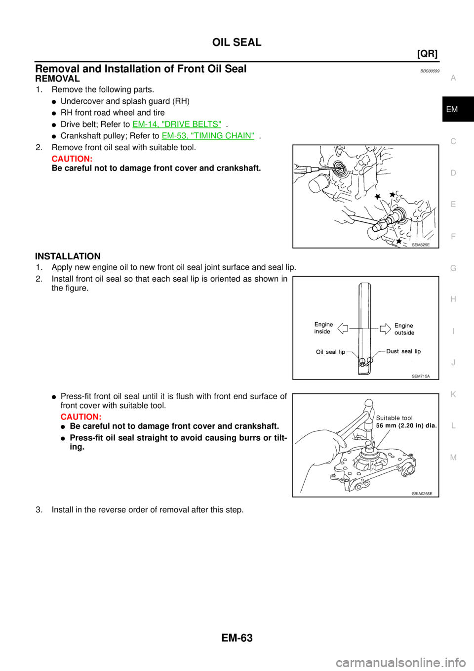
1. Apply new engine oil to new front oil seal joint surface and seal lip.
2. Install front oil seal so that each seal lip is oriented as shown in
the figure.
�Press-fit front oil seal until it is flush with front end surface of
front cover with suitable tool.
CAUTION:
�Be careful not to damage front cover and crankshaft.
�Press-fit oil seal straight to avoid causing burrs or tilt-
ing.
3. Install in the reverse order of removal after this step.
SEM829E
SEM715A
SBIA0266E