Page 2230 of 3502
EM-122
[VQ]
PREPARATION
PREPARATIONPFP:00002
Special Service Tools BBS004VI
Tool number
Tool nameDescription
ST0501S000
Engine stand assembly
1. ST05011000
Engine stand
2. ST05012000
BaseDisassembling and assembling engine
KV10106500
Engine stand shaft
KV10117000
Engine sub-attachmentKV10117000 has been replaced with
KV10117001 (KV10117000 is no longer in
production, but it is usable).
KV10117001
Engine sub-attachmentInstalling on cylinder block
KV10116200
Valve spring compressor
1. KV10115900
Attachment
2. KV10109220
AdapterDisassembling and assembling valve
mechanism
Part (1) is a component of KV10116200, but
Part (2) is not so.
KV10107902
Valve oil seal puller
1. KV10116100
Valve oil seal puller adapterRemoving valve oil seal
KV10115600
Valve oil seal driftInstalling valve oil seal
Use side A.
a: 20 (0.79) dia. d: 8 (0.31) dia.
b: 13 (0.51) dia. e: 10.7 (0.421)
c: 10.3 (0.406) dia. f: 5 (0.2)
Unit: mm (in)
NT042
NT028
NT373
NT372
PBIC1650E
S-NT605
S-NT603
Page 2235 of 3502
![NISSAN TEANA 2003 Service Manual NOISE, VIBRATION AND HARSHNESS (NVH) TROUBLESHOOTING
EM-127
[VQ]
C
D
E
F
G
H
I
J
K
L
MA
EM
Use the Chart Below to Help You Find the Cause of the Symptom.BBS004VL
1. Locate the area where noise occur](/manual-img/5/57392/w960_57392-2234.png "NISSAN TEANA 2003 Service Manual NOISE, VIBRATION AND HARSHNESS (NVH) TROUBLESHOOTING
EM-127
[VQ]
C
D
E
F
G
H
I
J
K
L
MA
EM
Use the Chart Below to Help You Find the Cause of the Symptom.BBS004VL
1. Locate the area where noise occur")
NOISE, VIBRATION AND HARSHNESS (NVH) TROUBLESHOOTING
EM-127
[VQ]
C
D
E
F
G
H
I
J
K
L
MA
EM
Use the Chart Below to Help You Find the Cause of the Symptom.BBS004VL
1. Locate the area where noise occurs.
2. Confirm the type of noise.
3. Specify the operating condition of engine.
4. Check specified noise source.
If necessary, repair or replace these parts.
A: Closely related B: Related C: Sometimes related —: Not relatedLocation
of noiseTy p e o f
noiseOperating condition of engine
Source of
noiseCheck itemRefer-
ence page Before
warm-
upAfter
warm-
upWhen
start-
ingWhen
idlingWhen
racingWhile
driving
Top of
engine
Rocker
cover
Cylinder
headTicking or
clickingCA—AB—Tappet
noiseValve clearanceEM-202
Rattle C A — A B CCamshaft
bearing
noiseCamshaft runout
Camshaft journal oil
clearanceEM-194EM-195
Crank-
shaft pul-
ley
Cylinder
block
(Side of
engine)
Oil panSlap or
knock—A—B B—Piston pin
noisePiston to piston pin oil
clearance
Connecting rod bush-
ing oil clearanceEM-245
EM-247
Slap or
rapA——BBAPiston
slap noisePiston to cylinder bore
clearance
Piston ring side clear-
ance
Piston ring end gap
Connecting rod bend
and torsionEM-249EM-246
EM-246
EM-247
Knock ABCBBBConnect-
ing rod
bearing
noiseConnecting rod bush-
ing oil clearance
Connecting rod bear-
ing oil clearanceEM-247EM-253
Knock A B — A B CMain
bearing
noiseMain bearing oil clear-
ance
Crankshaft runoutEM-252EM-251
Front of
engine
Timin g
chain
caseTapping or
tickingAA—BBBTimin g
chain and
chain ten-
sioner
noiseTiming chain cracks
and wear
Timing chain tensioner
operationEM-180
EM-173
Front of
engineSqueak-
ing or fizz-
ingAB—B—CDrive belts
(Sticking
or slip-
ping)Drive belts deflection
EM-128
CreakingABABABDrive belts
(Slipping)Idler pulley bearing
operation
Squall
CreakAB—BABWater
pump
noiseWater pump operationCO-46,
"WATER
PUMP"
Page 2282 of 3502
![NISSAN TEANA 2003 Service Manual EM-174
[VQ]
TIMING CHAIN
NOTE:
�This section describes procedures for removal/installation front timing chain case and timing chain related
parts, and rear timing chain case, when oil pan (upper) ne](/manual-img/5/57392/w960_57392-2281.png "NISSAN TEANA 2003 Service Manual EM-174
[VQ]
TIMING CHAIN
NOTE:
�This section describes procedures for removal/installation front timing chain case and timing chain related
parts, and rear timing chain case, when oil pan (upper) ne")
EM-174
[VQ]
TIMING CHAIN
NOTE:
�This section describes procedures for removal/installation front timing chain case and timing chain related
parts, and rear timing chain case, when oil pan (upper) needs to be removed/installed for engine overhaul,
etc.
�To removal/installation front timing chain case, timing chain, and timing chain related parts without remov-
ing oil pan (upper), refer to EM-163, "
FRONT TIMING CHAIN CASE" .
REMOVAL
1. Remove engine assembly from vehicle, and separate front suspension member and transaxle from
engine. Refer to EM-223, "
ENGINE ASSEMBLY" .
2. Install engine sub-attachment with engine stand shaft [SST: KV10117001 and KV10106500] to right side
of cylinder block, then lift engine, and mount it onto engine stand [SST: ST0501S000]. Refer to EM-228,
"CYLINDER BLOCK" .
3. Drain engine oil. Refer to LU-21, "
Changing Engine Oil" .
4. Drain engine coolant from inside engine. Refer to EM-229, "
DISASSEMBLY" .
5. Remove intake manifold collectors (upper and lower). Refer to EM-133, "
INTAKE MANIFOLD COLLEC-
TOR" .
6. Remove rocker covers (right and left banks). Refer to EM-160, "
ROCKER COVER" .
7. Remove oil pans (lower and upper) and oil strainer. Refer to EM-145, "
OIL PAN AND OIL STRAINER" .
8. Remove idler pulley and bracket.
9. Separate engine harness removing their brackets from front timing chain case
10. Remove right and left intake valve timing control covers.
�Loosen mounting bolts in the reverse order as shown in the
figure.
�U s e s e a l c u t t e r [ S S T: K V 1 0 1111 0 0 ] t o c u t l i q u i d g a s k e t f o r
removal.
CAUTION:
Shaft is internally jointed with camshaft sprocket (INT) cen-
ter hole. When removing, keep it horizontal until it is com-
pletely disconnected.
11. Remove collared O-ring from front timing chain case oil hole (left
and right sides).
1. O-ring 2. Timing chain tensioner (secondary) 3. Internal chain guide
4. Timing chain tensioner (secondary) 5. Camshaft sprocket (EXH) 6. Timing chain (secondary)
7. Timing chain (primary) 8. Camshaft sprocket (INT) 9. Slack guide
10. Timing chain tensioner (primary) 11. Camshaft sprocket (EXH) 12. Timing chain (secondary)
13. Camshaft sprocket (INT) 14. Crankshaft sprocket 15. Collared O-ring
16. Seal ring 17. Intake valve timing control cover 18. Chain tensioner cover
19. Intake valve timing control cover 20. Water pump cover 21. Front oil seal
22. Crankshaft pulley 23. Idler pulley 24. Idler pulley bracket
25. Center shaft 26. Washer 27. Front timing chain case
28. Rear timing chain case 29. Water drain plug (front) 30. Tension guide
PBIC0918E
PBIC2631E
Page 2290 of 3502
EM-182
[VQ]
TIMING CHAIN
b. Install new O-rings to cylinder head.
c. Apply liquid gasket with tube presser [SST: WS39930000] to rear timing chain case back side as shown in
the figure.
Use Genuine Liquid Gasket or equivalent.
CAUTION:
�For “A” in the figure, completely wipe out liquid gasket extended on a portion touching at
engine coolant.
�Apply liquid gasket on installation position of water pump and cylinder head very completely.
d. Align rear timing chain case and water pump assembly with dowel pins (right and left) on cylinder block
and install rear timing chain case.
�Make sure O-rings stay in place during installation to cylinder block and cylinder head.
SBIA0496E
PBIC2616E
Page 2301 of 3502
![NISSAN TEANA 2003 Service Manual CAMSHAFT
EM-193
[VQ]
C
D
E
F
G
H
I
J
K
L
MA
EM
2. Install engine sub-attachment with engine stand shaft [SST: KV10117001 and KV10106500] to right side
of cylinder block, then lift engine, and mount](/manual-img/5/57392/w960_57392-2300.png "NISSAN TEANA 2003 Service Manual CAMSHAFT
EM-193
[VQ]
C
D
E
F
G
H
I
J
K
L
MA
EM
2. Install engine sub-attachment with engine stand shaft [SST: KV10117001 and KV10106500] to right side
of cylinder block, then lift engine, and mount")
CAMSHAFT
EM-193
[VQ]
C
D
E
F
G
H
I
J
K
L
MA
EM
2. Install engine sub-attachment with engine stand shaft [SST: KV10117001 and KV10106500] to right side
of cylinder block, then lift engine, and mount it onto engine stand [SST: ST0501S000]. Refer to EM-228,
"CYLINDER BLOCK" .
3. Remove front timing chain case, camshaft sprocket, timing chain and rear timing chain case. Refer to EM-
173, "TIMING CHAIN" .
4. Remove camshaft position sensors (PHASE) (right and left
banks) from cylinder head back side.
CAUTION:
�Handle carefully to avoid dropping and shocks.
�Do not disassemble.
�Do not allow metal powder to adhere to magnetic part at
sensor tip.
�Do not place sensors in a location where they are
exposed to magnetism.
5. Remove intake valve timing control solenoid valves.
�Discard intake valve timing control solenoid valve gaskets and
use new gaskets for installation.
6. Remove camshaft brackets.
�Mark camshafts, camshaft brackets and bolts so they are placed in the same position and direction for
installation.
�Equally loosen camshaft bracket bolts in several steps in the
reverse order as shown in the figure.
7. Remove camshafts.
8. Remove valve lifters.
KBIA1046E
SEM443GA
PBIC2050E
Page 2311 of 3502
![NISSAN TEANA 2003 Service Manual CAMSHAFT
EM-203
[VQ]
C
D
E
F
G
H
I
J
K
L
MA
EM
b. Use feeler gauge, measure the clearance between valve lifter
and camshaft.
Valve clearance:
Unit: mm (in)
*: Approximately 80°C (176°F)
�By referr](/manual-img/5/57392/w960_57392-2310.png "NISSAN TEANA 2003 Service Manual CAMSHAFT
EM-203
[VQ]
C
D
E
F
G
H
I
J
K
L
MA
EM
b. Use feeler gauge, measure the clearance between valve lifter
and camshaft.
Valve clearance:
Unit: mm (in)
*: Approximately 80°C (176°F)
�By referr")
CAMSHAFT
EM-203
[VQ]
C
D
E
F
G
H
I
J
K
L
MA
EM
b. Use feeler gauge, measure the clearance between valve lifter
and camshaft.
Valve clearance:
Unit: mm (in)
*: Approximately 80°C (176°F)
�By referring to the figure, measure the valve clearances at
locations marked “×” as shown in the table below (locations
indicated in the figure) with feeler gauge.
�No. 1 cylinder at compression TDC
c. Rotate crankshaft by 240 degrees clockwise (when viewed from engine front) to align No. 3 cylinder at
TDC of its compression stroke.
NOTE:
�To align cylinder No.3 with the compression top dead center,
place matching marks (A) on the crank pulley (1) side and on
the cylinder block side at a point 240°counterclockwise from
the compression top dead center using the hex head of the
crank pulley mounting bolt as aguide.
SEM139D
Cold Hot * (reference data)
Intake 0.26 - 0.34 (0.010 - 0.013) 0.304 - 0.416 (0.012 - 0.016)
Exhaust 0.29 - 0.37 (0.011 - 0.015) 0.308 - 0.432 (0.012 - 0.017)
Measuring position (right bank) No. 1 CYL. No. 3 CYL. No. 5 CYL.
No. 1 cylinder at
compression TDCEXH×
INT×
Measuring position (left bank) No. 2 CYL. No. 4 CYL. No. 6 CYL.
No. 1 cylinder at
compression TDCINT×
EXH×
PBIC2054E
PBIC4628J
Page 2312 of 3502
EM-204
[VQ]
CAMSHAFT
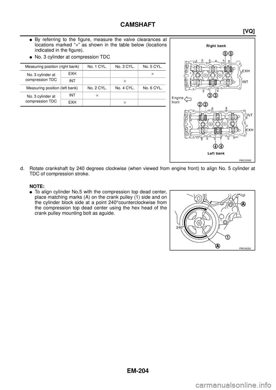
�By referring to the figure, measure the valve clearances at
locations marked “×” as shown in the table below (locations
indicated in the figure).
�No. 3 cylinder at compression TDC
d. Rotate crankshaft by 240 degrees clockwise (when viewed from engine front) to align No. 5 cylinder at
TDC of compression stroke.
NOTE:
�To align cylinder No.5 with the compression top dead center,
place matching marks (A) on the crank pulley (1) side and on
the cylinder block side at a point 240°counterclockwise from
the compression top dead center using the hex head of the
crank pulley mounting bolt as aguide.
Measuring position (right bank) No. 1 CYL. No. 3 CYL. No. 5 CYL.
No. 3 cylinder at
compression TDCEXH×
INT×
Measuring position (left bank) No. 2 CYL. No. 4 CYL. No. 6 CYL.
No. 3 cylinder at
compression TDCINT×
EXH ×
PBIC2055E
PBIC4628J
Page 2315 of 3502
![NISSAN TEANA 2003 Service Manual OIL SEAL
EM-207
[VQ]
C
D
E
F
G
H
I
J
K
L
MA
EM
OIL SEALPFP:00100
Removal and Installation of Valve Oil SealBBS004W3
REMOVAL
1. Remove engine assembly from vehicle, and separate front suspension memb](/manual-img/5/57392/w960_57392-2314.png "NISSAN TEANA 2003 Service Manual OIL SEAL
EM-207
[VQ]
C
D
E
F
G
H
I
J
K
L
MA
EM
OIL SEALPFP:00100
Removal and Installation of Valve Oil SealBBS004W3
REMOVAL
1. Remove engine assembly from vehicle, and separate front suspension memb")
OIL SEAL
EM-207
[VQ]
C
D
E
F
G
H
I
J
K
L
MA
EM
OIL SEALPFP:00100
Removal and Installation of Valve Oil SealBBS004W3
REMOVAL
1. Remove engine assembly from vehicle, and separate front suspension member and transaxle from
engine. Refer to EM-223, "
ENGINE ASSEMBLY" .
2. Install engine sub-attachment with engine stand shaft [SST: KV10117001 and KV10106500] to right side
of cylinder block, then lift engine, and mount it onto engine stand [SST: ST0501S000]. Refer to EM-228,
"CYLINDER BLOCK" .
3. Remove camshaft relating to valve oil seal to be removed. Refer to EM-192, "
CAMSHAFT" .
4. Remove valve lifters. Refer to EM-192, "
CAMSHAFT" .
5. Rotate crankshaft until the cylinder requiring new oil seals is at TDC. This will prevent valve from dropping
into cylinder.
6. Remove valve collet.
�Compress valve spring with valve spring compressor, attach-
ment, adapter (SST). Remove valve collet with magnet hand.
CAUTION:
When working, take care not to damage valve lifter holes.
7. Remove valve spring retainer and valve spring.
8. Remove valve oil seal using valve oil seal puller (SST).
INSTALLATION
1. Apply engine oil on new valve oil seal joint and seal lip.
2. Using valve oil seal drift (SST), press-fit valve seal to height “H”
shown in the figure.
NOTE:
Dimension “H”: Height measured before valve spring seat instal-
lation
3. Install in the reverse order of removal after this step.
PBIC1791E
PBIC1610E
Intake and exhaust : 14.3 - 14.9 mm (0.563 - 0.587 in)
PBIC1611E
![NISSAN TEANA 2003 Service Manual EM-122
[VQ]
PREPARATION
PREPARATIONPFP:00002
Special Service Tools BBS004VI
Tool number
Tool nameDescription
ST0501S000
Engine stand assembly
1. ST05011000
Engine stand
2. ST05012000
BaseDisassembli](/manual-img/5/57392/w960_57392-2229.png "NISSAN TEANA 2003 Service Manual EM-122
[VQ]
PREPARATION
PREPARATIONPFP:00002
Special Service Tools BBS004VI
Tool number
Tool nameDescription
ST0501S000
Engine stand assembly
1. ST05011000
Engine stand
2. ST05012000
BaseDisassembli")
![NISSAN TEANA 2003 Service Manual EM-182
[VQ]
TIMING CHAIN
b. Install new O-rings to cylinder head.
c. Apply liquid gasket with tube presser [SST: WS39930000] to rear timing chain case back side as shown in
the figure.
Use Genuine L](/manual-img/5/57392/w960_57392-2289.png "NISSAN TEANA 2003 Service Manual EM-182
[VQ]
TIMING CHAIN
b. Install new O-rings to cylinder head.
c. Apply liquid gasket with tube presser [SST: WS39930000] to rear timing chain case back side as shown in
the figure.
Use Genuine L")