2003 NISSAN ALMERA N16 oil pressure
[x] Cancel search: oil pressurePage 778 of 3189
![NISSAN ALMERA N16 2003 Electronic Repair Manual EC-448
[QG (WITHOUT EURO-OBD)]
TROUBLE DIAGNOSIS
Symptom Matrix Chart
EBS00KEV
SYSTEM — BASIC ENGINE CONTROL SYSTEM
SYMPTOM
Reference
page
HARD/NO START/RESTART (EXCP. HA)
ENGINE STALL
HESITATION/S NISSAN ALMERA N16 2003 Electronic Repair Manual EC-448
[QG (WITHOUT EURO-OBD)]
TROUBLE DIAGNOSIS
Symptom Matrix Chart
EBS00KEV
SYSTEM — BASIC ENGINE CONTROL SYSTEM
SYMPTOM
Reference
page
HARD/NO START/RESTART (EXCP. HA)
ENGINE STALL
HESITATION/S](/manual-img/5/57350/w960_57350-777.png)
EC-448
[QG (WITHOUT EURO-OBD)]
TROUBLE DIAGNOSIS
Symptom Matrix Chart
EBS00KEV
SYSTEM — BASIC ENGINE CONTROL SYSTEM
SYMPTOM
Reference
page
HARD/NO START/RESTART (EXCP. HA)
ENGINE STALL
HESITATION/SURGING/FLAT SPOT
SPARK KNOCK/DETONATION
LACK OF POWER/POOR ACCELERATION
HIGH IDLE/LOW IDLE
ROUGH IDLE/HUNTING
IDLING VIBRATION
SLOW/NO RETURN TO IDLE
OVERHEATS/WATER TEMPERATURE HIGH
EXCESSIVE FUEL CONSUMPTION
EXCESSIVE OIL CONSUMPTION
BATTERY DEAD (UNDER CHARGE)
Warranty symptom code AA AB AC AD AE AF AG AH AJ AK AL AM HA
Fuel Fuel pump circuit 11232 22 3 2EC-699
Fuel pressure regulator system334444444 4EC-427
Injector circuit 11232 22 2EC-693
Evaporative emission system 334444444 4EC-717
Air Positive crankcase ventilation sys-
tem334444444 41EC-720
Incorrect idle speed adjustment 33 1111 1EC-443
Electric throttle control actuator 112332222 2 2EC-575
,
EC-578
,
EC-585
,
EC-591
IgnitionIncorrect ignition timing adjustment33111 11 1EC-443
Ignition circuit 11222 22 2EC-660
Main power supply and ground circuit 22333 33 23EC-486
Mass air flow sensor circuit 11222 22 2EC-495
Engine coolant temperature sensor circuit 11222322312EC-501
Throttle position sensor circuit 12 22222 2EC-524
,
EC-530
,
EC-607
,
EC-613
,
EC-615
,
EC-624
Accelerator pedal position sensor circuit3212 2EC-536
,
EC-543
,
EC-617
Heated oxygen sensor 1 circuit 1232 22 2EC-506
,
EC-512
,
EC-647
Knock sensor circuit 2 2 3EC-550
Crankshaft position sensor (POS) circuit 2 2EC-554
Camshaft position sensor (PHASE) circuit 2 2EC-561
Vehicle speed signal circuit 2 3 3 3EC-677
Power steering pressure sensor circuit 2 3333EC-678
Page 779 of 3189
![NISSAN ALMERA N16 2003 Electronic Repair Manual TROUBLE DIAGNOSIS
EC-449
[QG (WITHOUT EURO-OBD)]
C
D
E
F
G
H
I
J
K
L
MA
EC
1 - 6: The numbers refer to the order of inspection.
(continued on next page)
SYSTEM — ENGINE MECHANICAL & OTHER
ECM 223333 NISSAN ALMERA N16 2003 Electronic Repair Manual TROUBLE DIAGNOSIS
EC-449
[QG (WITHOUT EURO-OBD)]
C
D
E
F
G
H
I
J
K
L
MA
EC
1 - 6: The numbers refer to the order of inspection.
(continued on next page)
SYSTEM — ENGINE MECHANICAL & OTHER
ECM 223333](/manual-img/5/57350/w960_57350-778.png)
TROUBLE DIAGNOSIS
EC-449
[QG (WITHOUT EURO-OBD)]
C
D
E
F
G
H
I
J
K
L
MA
EC
1 - 6: The numbers refer to the order of inspection.
(continued on next page)
SYSTEM — ENGINE MECHANICAL & OTHER
ECM 22333333333EC-568,
EC-571
Intake valve timing control solenoid valve cir-
cuit332 13223 3EC-683
PNP switch circuit 3 33333 3EC-689
Refrigerant pressure sensor circuit 2 3 3 3 3 4EC-705
Electrical load signal circuit 3 3 3 3EC-710
Air conditioner circuit223333333 3 2AT C - 2 9
SYMPTOM
Reference
page
HARD/NO START/RESTART (EXCP. HA)
ENGINE STALL
HESITATION/SURGING/FLAT SPOT
SPARK KNOCK/DETONATION
LACK OF POWER/POOR ACCELERATION
HIGH IDLE/LOW IDLE
ROUGH IDLE/HUNTING
IDLING VIBRATION
SLOW/NO RETURN TO IDLE
OVERHEATS/WATER TEMPERATURE HIGH
EXCESSIVE FUEL CONSUMPTION
EXCESSIVE OIL CONSUMPTION
BATTERY DEAD (UNDER CHARGE)
Warranty symptom code AA AB AC AD AE AF AG AH AJ AK AL AM HA
Fuel Fuel tank
5
5FE-4
Fuel piping 5 5 5 5 5 5 FE-4
Vapor lock—
Valve deposit
555555 5—
Poor fuel (Heavy weight gaso-
line, Low octane)—
Page 800 of 3189
![NISSAN ALMERA N16 2003 Electronic Repair Manual EC-470
[QG (WITHOUT EURO-OBD)]
TROUBLE DIAGNOSIS
THRTL SEN 1 [V]××●The throttle position sensor signal volt-
age is displayed.
THRTL SEN 2 [V]×
INT/A TEMP SE
[°C] or [°F]××
●The intake air NISSAN ALMERA N16 2003 Electronic Repair Manual EC-470
[QG (WITHOUT EURO-OBD)]
TROUBLE DIAGNOSIS
THRTL SEN 1 [V]××●The throttle position sensor signal volt-
age is displayed.
THRTL SEN 2 [V]×
INT/A TEMP SE
[°C] or [°F]××
●The intake air](/manual-img/5/57350/w960_57350-799.png)
EC-470
[QG (WITHOUT EURO-OBD)]
TROUBLE DIAGNOSIS
THRTL SEN 1 [V]××●The throttle position sensor signal volt-
age is displayed.
THRTL SEN 2 [V]×
INT/A TEMP SE
[°C] or [°F]××
●The intake air temperature (determined
by the signal voltage of the intake air
temperature sensor) is indicated.
START SIGNAL
[ON/OFF]××
●Indicates [ON/OFF] condition of the
starter signal computed from the signals
of the crankshaft position sensor (POS),
camshaft position sensor (PHASE) and
battery voltage.
●After starting the engine, [OFF] is
displayed regardless of the starter
signal.
CLSD THL POS
[ON/OFF]××
●Indicates idle position [ON/OFF] com-
puted by ECM according to the acceler-
ator pedal position sensor signal.
AIR COND SIG
[ON/OFF]××
●Indicates [ON/OFF] condition of the air
conditioner switch as determined by the
air conditioner signal.
P/N POSI SW
[ON/OFF]××
●Indicates [ON/OFF] condition from the
park/neutral position (PNP) switch sig-
nal.
PW/ST SIGNAL
[ON/OFF]××
●[ON/OFF] condition of the power steer-
ing oil pressure switch as determined by
the power steering oil pressure signal is
indicated.
LOAD SIGNAL
[ON/OFF]××
●Indicates [ON/OFF] condition from the
electrical load signal.
ON ... Rear window defogger switch is
ON and/or lighting switch is in 2nd posi-
tion.
OFF ... Both rear window defogger
switch and lighting switch are OFF.
IGNITION SW
[ON/OFF]×
●Indicates [ON/OFF] condition from igni-
tion switch.
HEATER FAN SW
[ON/OFF]×
●Indicates [ON/OFF] condition from the
heater fan switch signal.
BRAKE SW
[ON/OFF]×
●Indicates [ON/OFF] condition from the
stop lamp switch signal.
INJ PULSE-B1
[msec]×
●Indicates the actual fuel injection pulse
width compensated by ECM according
to the input signals.●When the engine is stopped, a
certain computed value is indi-
cated.
IGN TIMING
[BTDC]×
●Indicates the ignition timing computed
by ECM according to the input signals.●When the engine is stopped, a
certain value is indicated.
CAL/LD VALUE [%]
●“Calculated load value” indicates the
value of the current airflow divided by
peak airflow.
MASS AIRFLOW
[g·m/s]
●Indicates the mass airflow computed by
ECM according to the signal voltage of
the mass air flow sensor. Monitored item
[Unit]ECM
INPUT
SIG-
NALSMAIN
SIG-
NALSCAN
DIAG
SUP-
PORT
MNTRDescription Remarks
Page 927 of 3189
![NISSAN ALMERA N16 2003 Electronic Repair Manual DTC P1217 ENGINE OVER TEMPERATURE
EC-597
[QG (WITHOUT EURO-OBD)]
C
D
E
F
G
H
I
J
K
L
MA
EC
On Board Diagnosis LogicEBS00KJ3
If the cooling fan or another component in the cooling system mal NISSAN ALMERA N16 2003 Electronic Repair Manual DTC P1217 ENGINE OVER TEMPERATURE
EC-597
[QG (WITHOUT EURO-OBD)]
C
D
E
F
G
H
I
J
K
L
MA
EC
On Board Diagnosis LogicEBS00KJ3
If the cooling fan or another component in the cooling system mal](/manual-img/5/57350/w960_57350-926.png)
DTC P1217 ENGINE OVER TEMPERATURE
EC-597
[QG (WITHOUT EURO-OBD)]
C
D
E
F
G
H
I
J
K
L
MA
EC
On Board Diagnosis LogicEBS00KJ3
If the cooling fan or another component in the cooling system malfunctions, engine coolant temperature will
rise. When the engine coolant temperature reaches an abnormally high temperature condition, a malfunction
is indicated.
This self-diagnosis has the one trip detection logic.
CAUTION:
When a malfunction is indicated, be sure to replace the coolant. Refer to LC-11. Also, replace the
engine oil. Refer to LC-8.
1. Fill radiator with coolant up to specified level with a filling speed of 2 liters per minute. Be sure to
use coolant with the proper mixture ratio. Refer to MA-21.
2. After refilling coolant, run engine to ensure that no water-flow noise is emitted.
Overall Function CheckEBS00KJ4
Use this procedure to check the overall function of the cooling fan. During this check, a DTC might not be con-
firmed.
WARNING:
Never remove the radiator cap when the engine is hot. Serious burns could be caused by high pres-
sure fluid escaping from the radiator.
Wrap a thick cloth around cap. Carefully remove the cap by turning it a quarter turn to allow built-up
pressure to escape. Then turn the cap all the way off.
WITH CONSULT-II
1. Check the coolant level in the reservoir tank and radiator.
Allow engine to cool before checking coolant level.
If the coolant level in the reservoir tank and/or radiator is below
the proper range, skip the following steps and go to EC-600,
"Diagnostic Procedure" .
2. Confirm whether customer filled the coolant or not. If customer
filled the coolant, skip the following steps and go to EC-600,
"Diagnostic Procedure" .
3. Turn ignition switch “ON”.
DTC No. Trouble diagnosis name DTC detecting condition Possible cause
P1217
1217Engine over temperature
(Overheat)
●Cooling fan does not operate properly
(Overheat).
●Cooling fan system does not operate properly
(Overheat).
●Engine coolant was not added to the system
using the proper filling method.
●Harness or connectors
(The cooling fan circuit is open or
shorted.)
●Harness or connectors
(The CAN communication line is
open or shorted.)
●Cooling fan
●Radiator hose
●Radiator
●Radiator cap
●Water pump
●Thermostat
For more information, refer to EC-605,
"Main 12 Causes of Overheating" .
SEF621W
Page 1013 of 3189
![NISSAN ALMERA N16 2003 Electronic Repair Manual IVT CONTROL SOLENOID VALVE
EC-683
[QG (WITHOUT EURO-OBD)]
C
D
E
F
G
H
I
J
K
L
MA
EC
IVT CONTROL SOLENOID VALVEPFP:23796
DescriptionEBS00KLL
SYSTEM DESCRIPTION
*: This signal is sent to the ECM through NISSAN ALMERA N16 2003 Electronic Repair Manual IVT CONTROL SOLENOID VALVE
EC-683
[QG (WITHOUT EURO-OBD)]
C
D
E
F
G
H
I
J
K
L
MA
EC
IVT CONTROL SOLENOID VALVEPFP:23796
DescriptionEBS00KLL
SYSTEM DESCRIPTION
*: This signal is sent to the ECM through](/manual-img/5/57350/w960_57350-1012.png)
IVT CONTROL SOLENOID VALVE
EC-683
[QG (WITHOUT EURO-OBD)]
C
D
E
F
G
H
I
J
K
L
MA
EC
IVT CONTROL SOLENOID VALVEPFP:23796
DescriptionEBS00KLL
SYSTEM DESCRIPTION
*: This signal is sent to the ECM through CAN communication line.
This mechanism hydraulically controls cam phases continuously with the fixed operating angle of the intake
valve.
The ECM receives signals such as crankshaft position, camshaft position, engine speed, and engine coolant
temperature. Then, the ECM sends ON/OFF pulse duty signals to the intake valve timing control solenoid
valve depending on driving status. This makes it possible to control the shut/open timing of the intake valve to
increase engine torque in low/mid speed range and output in high-speed range.
COMPONENT DESCRIPTION
Intake valve timing control solenoid valve is activated by ON/OFF
pulse duty (ratio) signals from the ECM.
The intake valve timing control solenoid valve changes the oil
amount and direction of flow through intake valve timing control unit
or stops oil flow.
The longer pulse width advances valve angle.
The shorter pulse width retards valve angle.
When ON and OFF pulse widths become equal, the solenoid valve
stops oil pressure flow to fix the intake valve angle at the control
position.
CONSULT-II Reference Value in Data Monitor ModeEBS00KLM
Specification data are reference values.
Sensor Input signal to ECM ECM function Actuator
Crankshaft position sensor (POS)
Engine speed
Intake valve
timing controlIntake valve timing control
solenoid valve Camshaft position sensor (PHASE)
Engine coolant temperature sensor Engine coolant temperature
Vehicle speed signal
*Vehicle speed
MBIB0121E
PBIB0195E
Page 1076 of 3189

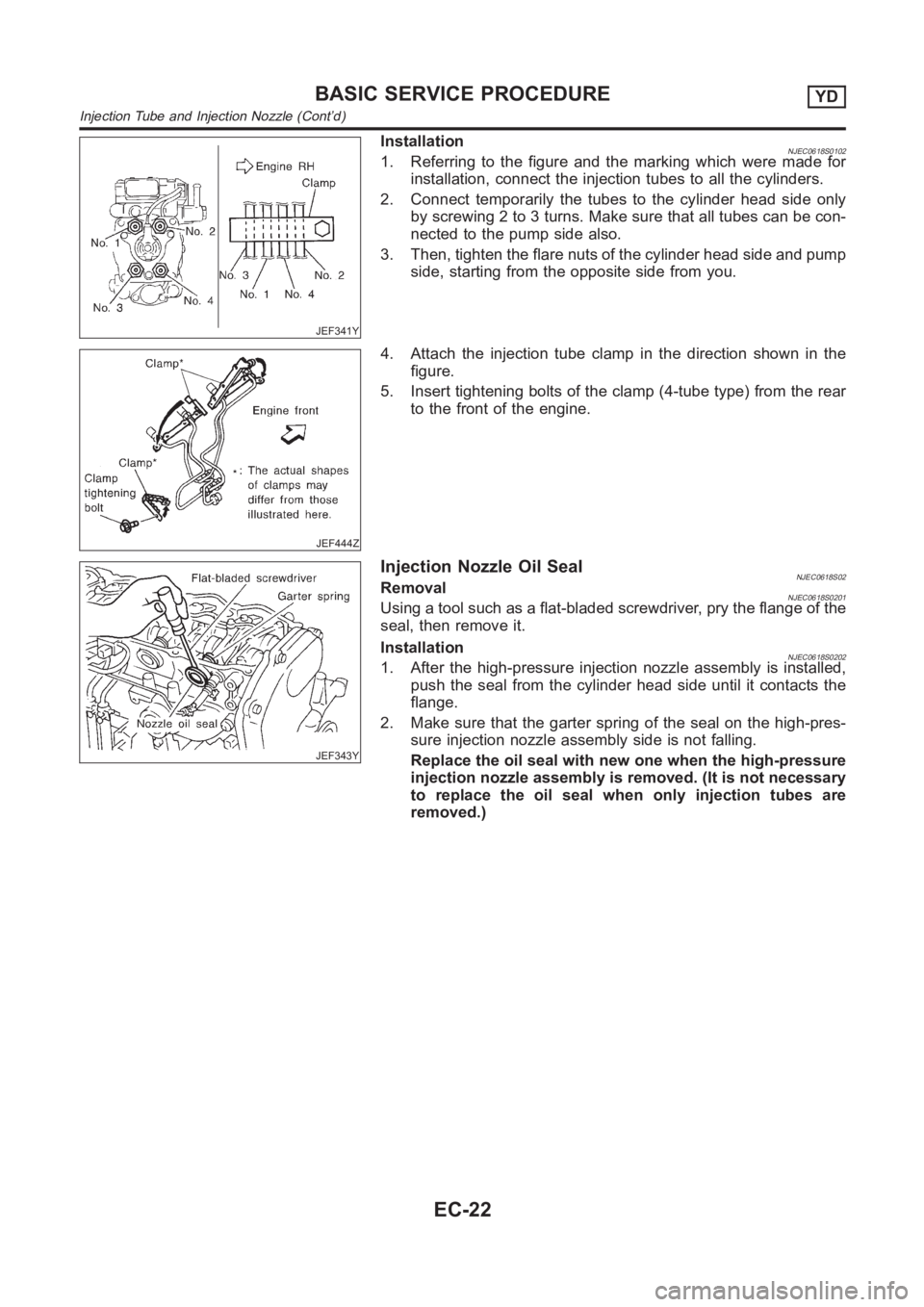
JEF341Y
InstallationNJEC0618S01021. Referring to the figure and the marking which were made for
installation, connect the injection tubes to all the cylinders.
2. Connect temporarily the tubes to the cylinder head side only
by screwing 2 to 3 turns. Make sure that all tubes can be con-
nected to the pump side also.
3. Then, tighten the flare nuts of the cylinder head side and pump
side, starting from the opposite side from you.
JEF444Z
4. Attach the injection tube clamp in the direction shown in the
figure.
5. Insert tightening bolts of the clamp (4-tube type) from the rear
to the front of the engine.
JEF343Y
Injection Nozzle Oil SealNJEC0618S02RemovalNJEC0618S0201Using a tool such as a flat-bladed screwdriver, pry the flange of the
seal, then remove it.
Installation
NJEC0618S02021. After the high-pressure injection nozzle assembly is installed,
push the seal from the cylinder head side until it contacts the
flange.
2. Make sure that the garter spring of the seal on the high-pres-
sure injection nozzle assembly side is not falling.
Replace the oil seal with new one when the high-pressure
injection nozzle assembly is removed. (It is not necessary
to replace the oil seal when only injection tubes are
removed.)
BASIC SERVICE PROCEDUREYD
Injection Tube and Injection Nozzle (Cont’d)
EC-22
Page 1108 of 3189

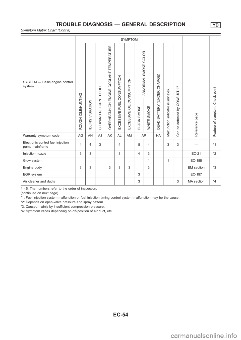
SYSTEM — Basic engine control
systemSYMPTOM
Reference page
Feature of symptom, Check pointROUGH IDLE/HUNTING
IDLING VIBRATION
SLOW/NO RETURN TO IDLE
OVERHEAT/HIGH ENGINE COOLANT TEMPERATURE
EXCESSIVE FUEL CONSUMPTION
EXCESSIVE OIL CONSUMPTION
ABNORMAL SMOKE COLOR
DEAD BATTERY (UNDER CHARGE)
Malfunction indicator illuminates.
Can be detected by CONSULT-II?BLACK SMOKE
WHITE SMOKEWarranty symptom code AG AH AJ AK AL AM AP HA
Electronic control fuel injection
pump mainframe44345433—*1
Injection nozzle 3 3 3 4 3 EC-21 *2
Glow system 1 1 EC-188
Engine body 3 3 3 3 3 3 EM section *3
EGR system 3 EC-197
Air cleaner and ducts 3 3 MA section *4
1 - 5: The numbers refer to the order of inspection.
(continued on next page)
*1: Fuel injection system malfunction or fuel injection timing control system malfunction may be the cause.
*2: Depends on open-valve pressure and spray pattern.
*3: Caused mainly by insufficient compression pressure.
*4: Symptom varies depending on off-position of air duct, etc.
TROUBLE DIAGNOSIS — GENERAL DESCRIPTIONYD
Symptom Matrix Chart (Cont’d)
EC-54
Page 1300 of 3189

NJCL0004
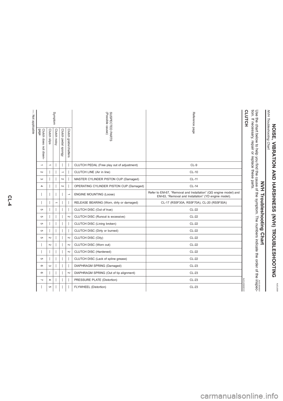
NVH Troubleshooting Chart
NJCL0004S01
Use the chart below to help you find the cause of the symptom. The numbers indicate the order of the inspec-
tion. If necessary, repair or replace these parts.CLUTCH
NJCL0004S0101
Reference page
CL-9
CL-10
CL-11
CL-14
Refer to EM-67, “Removal and Installation” (QG engine model) and
EM-63, “Removal and Installation” (YD engine model).
CL-17 (RS5F30A, RS5F70A), CL-20 (RS5F50A)
CL-22
CL-22
CL-22
CL-22
CL-22
CL-22
CL-22
CL-22
CL-23
CL-23
CL-23
CL-23
SUSPECTED PARTS
(Possible cause)
CLUTCH PEDAL (Free play out of adjustment)
CLUTCH LINE (Air in line)
MASTER CYLINDER PISTON CUP (Damaged)
OPERATING CYLINDER PISTON CUP (Damaged)
ENGINE MOUNTING (Loose)
RELEASE BEARING (Worn, dirty or damaged)
CLUTCH DISC (Out of true)
CLUTCH DISC (Runout is excessive)
CLUTCH DISC (Lining broken)
CLUTCH DISC (Dirty or burned)
CLUTCH DISC (Oily)
CLUTCH DISC (Worn out)
CLUTCH DISC (Hardened)
CLUTCH DISC (Lack of spline grease)
DIAPHRAGM SPRING (Damaged)
DIAPHRAGM SPRING (Out of tip alignment)
PRESSURE PLATE (Distortion)
FLYWHEEL (Distortion)
SymptomClutch grabs/chatters———— 1 —— 2 —— 2 2 2 —— 2 ——
Clutch pedal spongy — 1 2 2 ——————————————
Clutch noisy———— — 1 ————————————
Clutch slips 1 — — — —————— 2 2 —— 3 — 4 5
Clutch does not disen-
gage1234 ——55555——5667—
—: Not applicable
NOISE, VIBRATION AND HARSHNESS (NVH) TROUBLESHOOTING
NVH Troubleshooting Chart
CL-4