2003 NISSAN ALMERA N16 oil pressure
[x] Cancel search: oil pressurePage 1313 of 3189
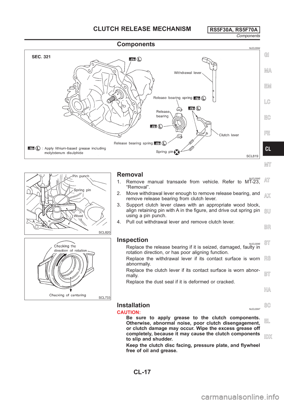
ComponentsNJCL0044
SCL819
SCL820
RemovalNJCL00451. Remove manual transaxle from vehicle. Refer to MT-23,
“Removal”.
2. Move withdrawal lever enough to remove release bearing, and
remove release bearing from clutch lever.
3. Support clutch lever claws with an appropriate wood block,
align retaining pin with A in the figure, and drive out spring pin
using a pin punch.
4. Pull out withdrawal lever and remove clutch lever.
SCL733
InspectionNJCL0046Replace the release bearing if it is seized, damaged, faulty in
rotation direction, or has poor aligning function.
Replace the withdrawal lever if its contact surface is worn
abnormally.
Replace the clutch lever if its contact surface is worn abnor-
mally.
Replace the dust seal if it is deformed or cracked.
InstallationNJCL0047CAUTION:
Be sure to apply grease to the clutch components.
Otherwise, abnormal noise, poor clutch disengagement,
or clutch damage may occur. Wipe the excess grease off
completely, because it may cause the clutch components
to slip and shudder.
Keep the clutch disc facing, pressure plate, and flywheel
free of oil and grease.
GI
MA
EM
LC
EC
FE
MT
AT
AX
SU
BR
ST
RS
BT
HA
SC
EL
IDX
CLUTCH RELEASE MECHANISMRS5F30A, RS5F70A
Components
CL-17
Page 1316 of 3189
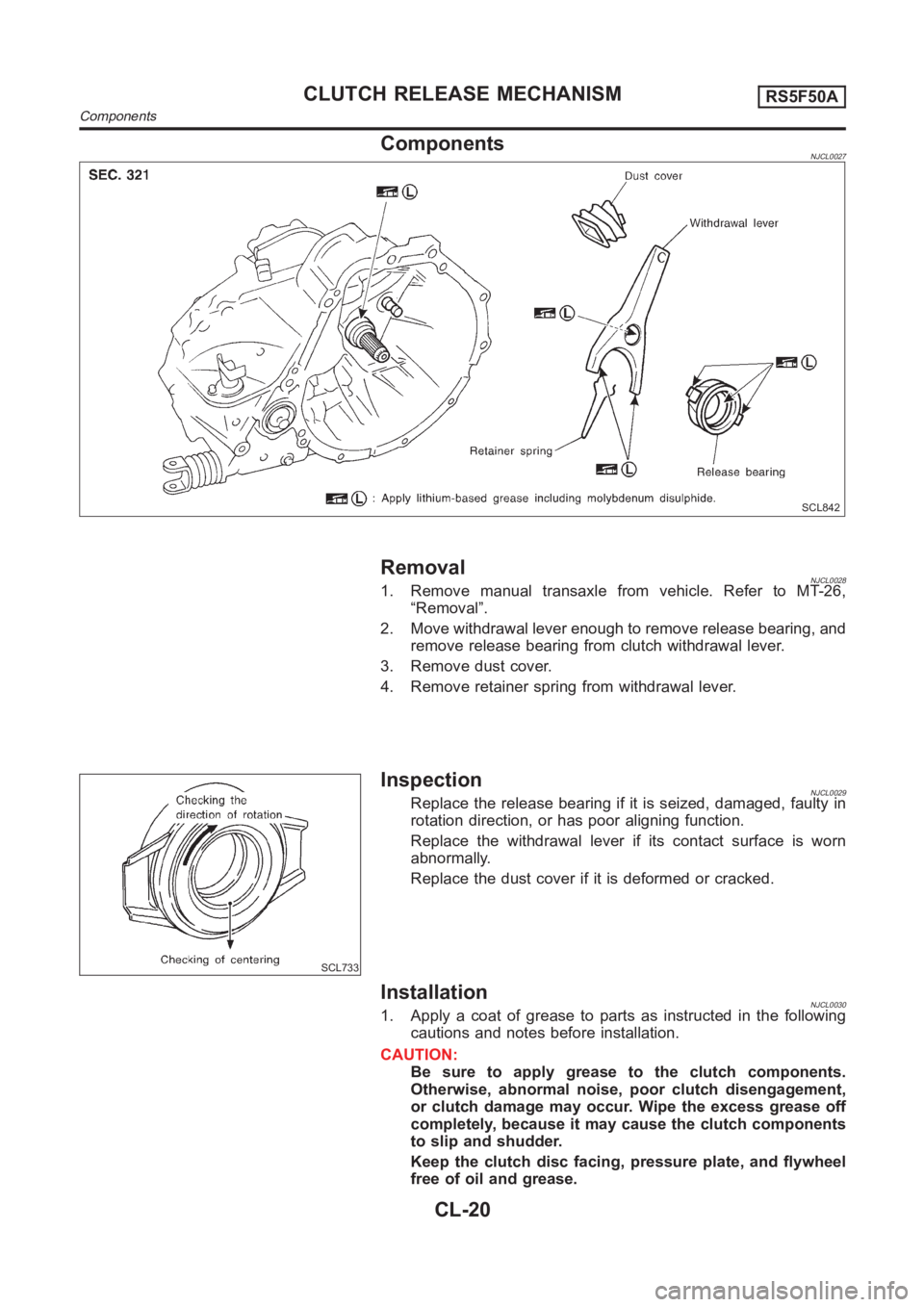
ComponentsNJCL0027
SCL842
RemovalNJCL00281. Remove manual transaxle from vehicle. Refer to MT-26,
“Removal”.
2. Move withdrawal lever enough to remove release bearing, and
remove release bearing from clutch withdrawal lever.
3. Remove dust cover.
4. Remove retainer spring from withdrawal lever.
SCL733
InspectionNJCL0029Replace the release bearing if it is seized, damaged, faulty in
rotation direction, or has poor aligning function.
Replace the withdrawal lever if its contact surface is worn
abnormally.
Replace the dust cover if it is deformed or cracked.
InstallationNJCL00301. Apply a coat of grease to parts as instructed in the following
cautions and notes before installation.
CAUTION:
Be sure to apply grease to the clutch components.
Otherwise, abnormal noise, poor clutch disengagement,
or clutch damage may occur. Wipe the excess grease off
completely, because it may cause the clutch components
to slip and shudder.
Keep the clutch disc facing, pressure plate, and flywheel
free of oil and grease.
CLUTCH RELEASE MECHANISMRS5F50A
Components
CL-20
Page 1459 of 3189
AT-3
D
E
F
G
H
I
J
K
L
MA
B
AT Line Pressure Test ............................................... 265
Road Test ............................................................. 266
TROUBLE DIAGNOSIS — GENERAL DESCRIP-
TION ........................................................................ 283
Symptom Chart .................................................... 283
TCM Terminals and Reference Value ................... 302
CAN COMMUNICATION ........................................ 305
System Description .............................................. 305
CAN Communication Unit .................................... 305
TROUBLE DIAGNOSES FOR SYMPTOMS .......... 307
Wiring Diagram — AT — NONDTC ...................... 307
1. O/D OFF Indicator Lamp Does Not Come On . 309
2. Engine Cannot Be Started In “P” and “N” Position . 309
3. In “P” Position, Vehicle Moves Forward Or Back-
ward When Pushed .............................................. 310
4. In “N” Position, Vehicle Moves .......................... 311
5. Large Shock. “N” → “R” Position ...................... 312
6. Vehicle Does Not Creep Backward In “R” Position . 313
7. Vehicle Does Not Creep Forward In “D”, “2” Or
“1” Position ........................................................... 316
8. Vehicle Cannot Be Started From D
1 ................. 317
9. A/T Does Not Shift: D
1→ D2 Or Does Not Kick
down: D
4→ D2 ..................................................... 320
10. A/T Does Not Shift: D
2→ D3 ......................... 322
11. A/T Does Not Shift: D
3→ D4 .......................... 324
12. A/T Does Not Perform Lock-up ...................... 326
13. A/T Does Not Hold Lock-up Condition ........... 326
14. Lock-up Is Not Released ................................ 328
15. Engine Speed Does Not Return To Idle (Light
Braking D
4→ D3 ) ................................................ 328
16. Vehicle Does Not Start From D
1 ..................... 330
17. A/T Does Not Shift: D
4→ D3 , When Overdrive
Control Switch “ON” → “OFF” .............................. 330
18. A/T Does Not Shift: D
3→ 22 , When Selector
Lever “D” → “2” Position ...................................... 331
19. A/T Does Not Shift: 2
2→ 11 , When Selector
Lever “2” → “1” Position ....................................... 332
20. Vehicle Does Not Decelerate By Engine Brake . 333
21. TCM Self-diagnosis Does Not Activate (PNP &
Overdrive Control Switches, and Throttle Position
Sensor Circuit Checks) ........................................ 333
ALL
MAIN POWER SUPPLY AND GROUND CIRCUIT . 340
Wiring Diagram — AT — MAIN ............................ 340
Diagnostic Procedure ........................................... 341
VEHICLE SPEED SENSOR - A/T (REVOLUTION
SENSOR) ................................................................ 343
Description ........................................................... 343
Wiring Diagram — AT — VSSAT ......................... 345
Diagnostic Procedure ........................................... 346
DTC VEHICLE SPEED SENSOR MTR .................. 348
Description ........................................................... 348
Wiring Diagram — AT — VSSMTR ...................... 350
Diagnostic Procedure ........................................... 351
ACCELE RATOR PEDAL POSITION (APP) SEN-
SOR ........................................................................ 352
Description ........................................................... 352Wiring Diagram — AT — TPS ..............................354
Diagnostic Procedure ...........................................355
SHIFT SOLENOID VALVE A ..................................357
Description ............................................................357
Wiring Diagram — AT — SSV/A ...........................359
Diagnostic Procedure ...........................................360
Component Inspection ..........................................360
SHIFT SOLENOID VALVE B ..................................362
Description ............................................................362
Wiring Diagram — AT — SSV/B ...........................364
Diagnostic Procedure ...........................................365
Component Inspection ..........................................365
OVERRUN CLUTCH SOLENOID VALVE ...............367
Description ............................................................367
Wiring Diagram — AT — OVRCSV ......................369
Diagnostic Procedure ...........................................370
Component Inspection ..........................................371
TORQUE CONVERTER CLUTCH SOLENOID
VALVE .....................................................................372
Description ............................................................372
Wiring Diagram — AT — TCV ..............................374
Diagnostic Procedure ...........................................375
Component Inspection ..........................................375
BATT/FLUID TEMP SEN (A/T FLUID TEMP SEN-
SOR CIRCUIT AND TCM POWER SOURCE) .......377
Description ............................................................377
Wiring Diagram — AT — BA/FTS .........................379
Diagnostic Procedure ...........................................380
Component Inspection ..........................................382
ENGINE SPEED SIGNAL .......................................383
Description ............................................................383
Wiring Diagram — AT — ENGSS .........................385
Diagnostic Procedure ...........................................386
LINE PRESSURE SOLENOID VALVE ...................388
Description ............................................................388
Wiring Diagram — AT — LPSV ............................390
Diagnostic Procedure ...........................................391
Component Inspection ..........................................393
CAN COMMUNICATION LINE ...............................395
Description ............................................................395
On Board Diagnosis Logic ....................................395
Self-Diagnosis Code Confirmation Procedure ......395
Wiring Diagram — AT — CAN ..............................396
Diagnostic Procedure ...........................................397
A/T SHIFT LOCK SYSTEM ....................................398
Description ............................................................398
Shift Lock System Electrical Parts Location .........398
Wiring Diagram — SHIFT — ................................399
Diagnostic Procedure ...........................................400
KEY INTERLOCK CABLE ......................................404
Components .........................................................404
Removal ...............................................................404
Installation ............................................................405
ON-VEHICLE SERVICE ..........................................406
Control Valve Assembly and Accumulators ..........406
Control Cable Adjustment .....................................408
Park/Neutral Position (PNP) Switch Adjustment ..408
Differential Side Oil Seal Replacement ................409
Revolution Sensor Replacement ..........................409
Page 1460 of 3189
AT-4
REMOVAL AND INSTALLATION ...........................410
Removal ...............................................................410
Installation .............................................................411
OVERHAUL .............................................................413
Output Shaft, Idler Gear, Reduction Pinion Gear and
Bearing Retainer ...................................................413
Oil Channel ...........................................................416
Locations of Adjusting Shims, Needle Bearings,
Thrust Washers and Snap Rings ..........................417
DISASSEMBLY .......................................................418
Disassembly .........................................................418
REPAIR FOR COMPONENT PARTS ......................432
Manual Shaft ........................................................432
Oil Pump ...............................................................435
Control Valve Assembly ........................................439
Control Valve Upper Body ....................................449
Control Valve Lower Body ....................................453
Reverse Clutch .....................................................455
High Clutch ...........................................................459
Forward and Overrun Clutches ............................464
Low & Reverse Brake ...........................................470
Rear Internal Gear, Forward Clutch Hub and Over-
run Clutch Hub ......................................................474
Output Shaft, Idler Gear, Reduction Pinion Gear and
Bearing Retainer ...................................................478
Band Servo Piston Assembly ...............................483
Final Drive ............................................................488
ASSEMBLY .............................................................493
Assembly (1) .........................................................493Adjustment (1) .......................................................494
Assembly (2) .........................................................500
Adjustment (2) .......................................................504
Assembly (3) .........................................................508
SERVICE DATA AND SPECIFICATIONS (SDS) ....515
General Specifications ......................................... .515
Shift Schedule .......................................................515
Stall Revolution .....................................................515
Line Pressure ........................................................515
Control Valves .......................................................516
Clutch and Brakes .................................................516
Clutch and Brake Return Springs .........................518
Oil Pump ......................................................
.........518
Input Shaft .............................................................518
Planetary carrier ....................................................518
Final Drive .............................................................519
Reduction Pinion Gear ..........................................520
Output Shaft ..........................................................522
Bearing Retainer ...................................................523
Total End Play .......................................................523
Reverse Clutch End Play ......................................523
Accumulator ..........................................................523
Band Servo ...........................................................524
Removal and Installation .......................................524
Shift Solenoid Valves ............................................524
Solenoid Valves ....................................................524
A/T Fluid Temperature Sensor ..............................524
Revolution Sensor .................................................524
Dropping Resistor .................................................524
Page 1465 of 3189
PREPARATION
AT-9
D
E
F
G
H
I
J
K
L
MA
B
AT
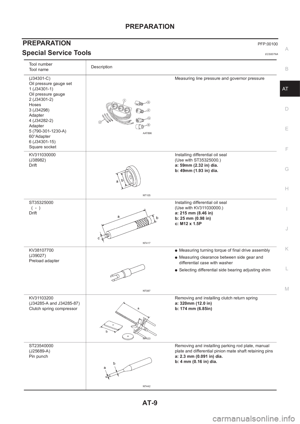
PREPARATIONPFP:00100
Special Service ToolsECS007NA
Tool number
Tool nameDescription
(J34301-C)
Oil pressure gauge set
1 (J34301-1)
Oil pressure gauge
2 (J34301-2)
Hoses
3 (J34298)
Adapter
4 (J34282-2)
Adapter
5 (790-301-1230-A)
60°Adapter
6 (J34301-15)
Square socketMeasuring line pressure and governor pressure
KV311030000
(J38982)
Drift Installing differential oil seal
(Use with ST35325000.)
a: 59mm (2.32 in) dia.
b: 49mm (1.93 in) dia.
ST35325000
( - )
Drift Installing differential oil seal
(Use with KV311030000.)
a: 215 mm (8.46 in)
b: 25 mm (0.98 in)
c: M12 x 1.5P
KV38107700
(J39027)
Preload adapter
●Measuring turning torque of final drive assembly
●Measuring clearance between side gear and
differential case with washer
●Selecting differential side bearing adjusting shim
KV31103200
(J34285-A and J34285-87)
Clutch spring compressor Removing and installing clutch return spring
a: 320mm (12.0 in)
b: 174 mm (6.85in)
ST23540000
(J25689-A)
Pin punch Removing and installing parking rod plate, manual
plate and differential pinion mate shaft retaining pins
a: 2.3 mm (0.091 in) dia.
b: 4 mm (0.16 in) dia.
AAT896
NT105
NT417
NT087
NT423
NT442
Page 1475 of 3189
OVERALL SYSTEM
AT-19
D
E
F
G
H
I
J
K
L
MA
B
AT
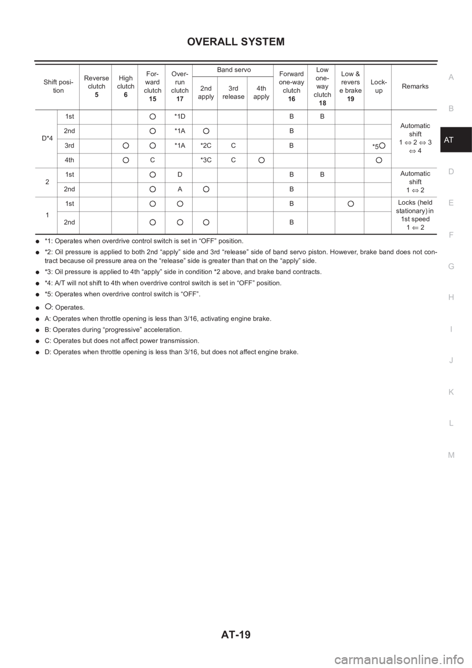
●*1: Operates when overdrive control switch is set in “OFF” position.
●*2: Oil pressure is applied to both 2nd “apply” side and 3rd “release” side of band servo piston. However, brake band does not con-
tract because oil pressure area on the “release” side is greater than that on the “apply” side.
●*3: Oil pressure is applied to 4th “apply” side in condition *2 above, and brake band contracts.
●*4: A/T will not shift to 4th when overdrive control switch is set in “OFF” position.
●*5: Operates when overdrive control switch is “OFF”.
●: Operates.
●A: Operates when throttle opening is less than 3/16, activating engine brake.
●B: Operates during “progressive” acceleration.
●C: Operates but does not affect power transmission.
●D: Operates when throttle opening is less than 3/16, but does not affect engine brake. D*41st *1D B B
Automatic
shift
1⇔ 2 ⇔ 3
⇔ 4 2nd *1A B
3rd *1A *2C C B
*5
4th C *3C C
21st D B BAutomatic
shift
1⇔ 2 2nd A B
11stBLocks (held
stationary) in
1st speed
1⇐ 2 2ndB Shift posi-
tionReverse
clutch
5High
clutch
6For-
ward
clutch
15Over-
run
clutch
17Band servo
Forward
one-way
clutch
16Low
one-
way
clutch
18Low &
revers
e brake
19Lock-
upRemarks
2nd
apply3rd
release4th
apply
Page 1486 of 3189
AT-30
OVERALL SYSTEM
SHIFT CONTROL
The shift is regulated entirely by electronic control to accommodate vehicle speed and varying engine opera-
tions. This is accomplished by electrical signals transmitted by the revolution sensor and throttle position sen-
sor. This results in improved acceleration performance and fuel economy.
Control of Shift Solenoid Valves A and B
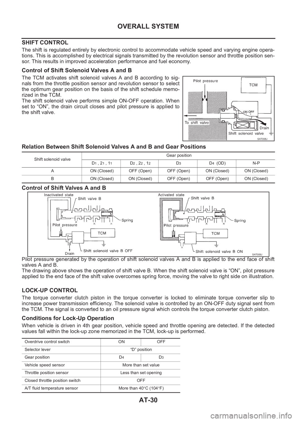
The TCM activates shift solenoid valves A and B according to sig-
nals from the throttle position sensor and revolution sensor to select
the optimum gear position on the basis of the shift schedule memo-
rized in the TCM.
The shift solenoid valve performs simple ON-OFF operation. When
set to “ON”, the drain circuit closes and pilot pressure is applied to
the shift valve.
Relation Between Shift Solenoid Valves A and B and Gear Positions
Control of Shift Valves A and B
Pilot pressure generated by the operation of shift solenoid valves A and B is applied to the end face of shift
valves A and B.
The drawing above shows the operation of shift valve B. When the shift solenoid valve is “ON”, pilot pressure
applied to the end face of the shift valve overcomes spring force, moving the valve to right side on illustration.
LOCK-UP CONTROL
The torque converter clutch piston in the torque converter is locked to eliminate torque converter slip to
increase power transmission efficiency. The solenoid valve is controlled by an ON-OFF duty signal sent from
the TCM. The signal is converted to an oil pressure signal which controls the torque converter clutch piston.
Conditions for Lock-Up Operation
When vehicle is driven in 4th gear position, vehicle speed and throttle opening are detected. If the detected
values fall within the lock-up zone memorized in the TCM, lock-up is performed.
SAT008J
Shift solenoid valveGear position
D1 , 21 , 11D2 , 22 , 12D3D4 (OD) N-P
A ON (Closed) OFF (Open) OFF (Open) ON (Closed) ON (Closed)
B ON (Closed) ON (Closed) OFF (Open) OFF (Open) ON (Closed)
SAT009J
Overdrive control switch ON OFF
Selector lever “D” position
Gear position D
4D3
Vehicle speed sensor More than set value
Throttle position sensor Less than set opening
Closed throttle position switch OFF
A/T fluid temperature sensor More than 40°C (104°F)
Page 1490 of 3189
AT-34
OVERALL SYSTEM
Control Valve
ECS007NL
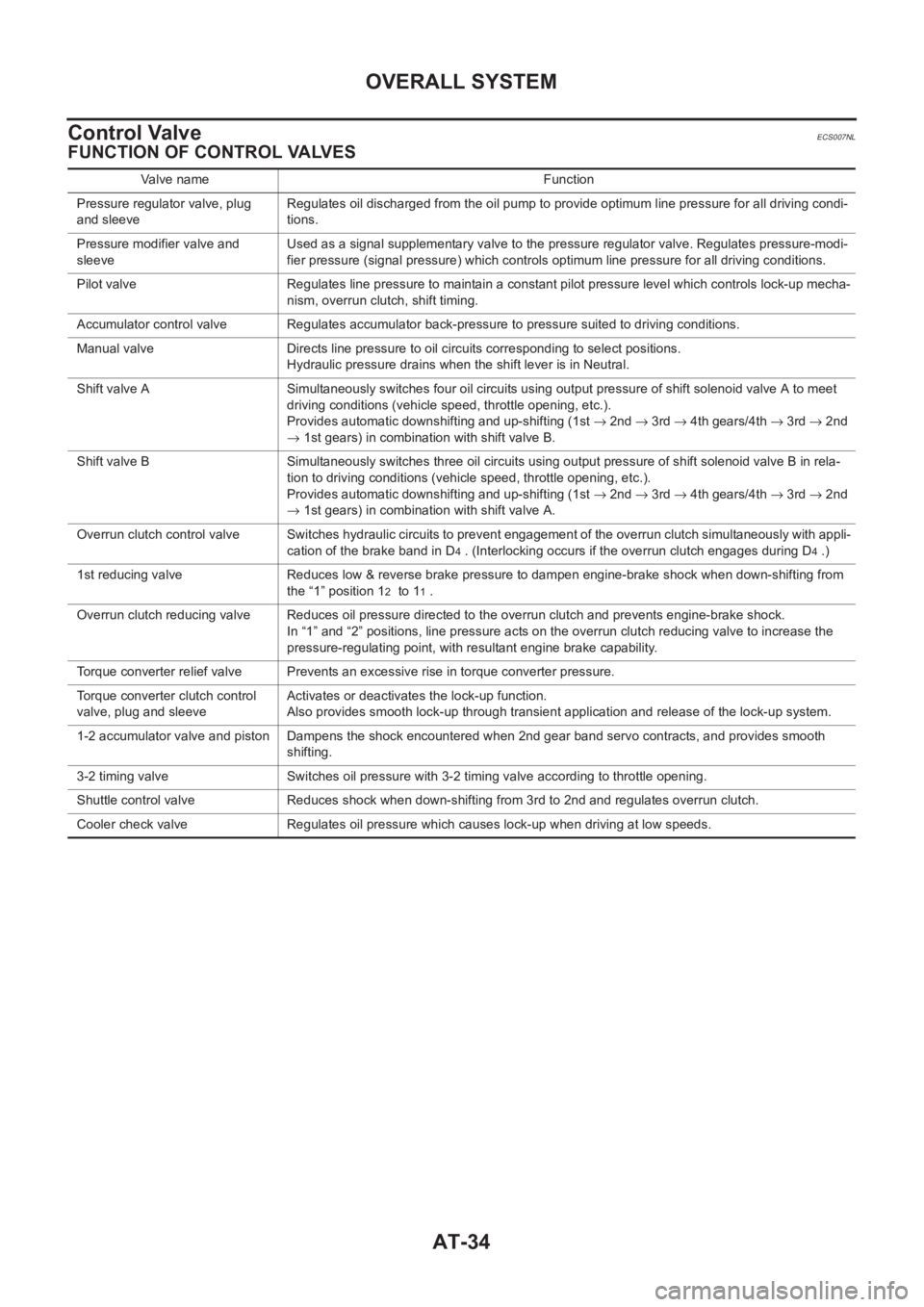
FUNCTION OF CONTROL VALVES
Valve name Function
Pressure regulator valve, plug
and sleeveRegulates oil discharged from the oil pump to provide optimum line pressure for all driving condi-
tions.
Pressure modifier valve and
sleeveUsed as a signal supplementary valve to the pressure regulator valve. Regulates pressure-modi-
fier pressure (signal pressure) which controls optimum line pressure for all driving conditions.
Pilot valve Regulates line pressure to maintain a constant pilot pressure level which controls lock-up mecha-
nism, overrun clutch, shift timing.
Accumulator control valve Regulates accumulator back-pressure to pressure suited to driving conditions.
Manual valve Directs line pressure to oil circuits corresponding to select positions.
Hydraulic pressure drains when the shift lever is in Neutral.
Shift valve A Simultaneously switches four oil circuits using output pressure of shift solenoid valve A to meet
driving conditions (vehicle speed, throttle opening, etc.).
Provides automatic downshifting and up-shifting (1st → 2nd → 3rd → 4th gears/4th → 3rd → 2nd
→ 1st gears) in combination with shift valve B.
Shift valve B Simultaneously switches three oil circuits using output pressure of shift solenoid valve B in rela-
tion to driving conditions (vehicle speed, throttle opening, etc.).
Provides automatic downshifting and up-shifting (1st → 2nd → 3rd → 4th gears/4th → 3rd → 2nd
→ 1st gears) in combination with shift valve A.
Overrun clutch control valve Switches hydraulic circuits to prevent engagement of the overrun clutch simultaneously with appli-
cation of the brake band in D
4 . (Interlocking occurs if the overrun clutch engages during D4 .)
1st reducing valve Reduces low & reverse brake pressure to dampen engine-brake shock when down-shifting from
the “1” position 1
2 to 11 .
Overrun clutch reducing valve Reduces oil pressure directed to the overrun clutch and prevents engine-brake shock.
In “1” and “2” positions, line pressure acts on the overrun clutch reducing valve to increase the
pressure-regulating point, with resultant engine brake capability.
Torque converter relief valve Prevents an excessive rise in torque converter pressure.
Torque converter clutch control
valve, plug and sleeveActivates or deactivates the lock-up function.
Also provides smooth lock-up through transient application and release of the lock-up system.
1-2 accumulator valve and piston Dampens the shock encountered when 2nd gear band servo contracts, and provides smooth
shifting.
3-2 timing valve Switches oil pressure with 3-2 timing valve according to throttle opening.
Shuttle control valve Reduces shock when down-shifting from 3rd to 2nd and regulates overrun clutch.
Cooler check valve Regulates oil pressure which causes lock-up when driving at low speeds.