Page 2685 of 3189
NATS RELEASE SIGNAL CHECK=NJEL0477S09
1 CHECK NATS SIGNAL CIRCUIT
1. Disconnect battery cable (−) terminal.
2. Disconnect time control unit connector and NATS IMMU connector.
SEL478X
OK or NG
OK GO TO 2.
NG Repair harness.
2 CHECK NATS RELEASE SIGNAL
1. Connect time control unit connector and NATS IMMU connector.
2. Connect battery cable (−) terminal.
3. Check voltage between time control unit terminal 26 and ground.
SEL479X
OK or NG
OK Replace super lock control unit.
NG Check NATS system.
GI
MA
EM
LC
EC
FE
CL
MT
AT
AX
SU
BR
ST
RS
BT
HA
SC
IDX
POWER DOOR LOCK — SUPER LOCK —
Trouble Diagnoses/YD Engine Models without Common Rail and K9K Engine Models (Cont’d)
EL-349
Page 2687 of 3189
IGNITION SWITCH “ON” CIRCUIT CHECK=NJEL0477S11
1 CHECK IGNITION ON SIGNAL
Check voltage between time control unit terminal 1 and ground.
SEL429X
OK or NG
OK Ignition switch “ON” circuit is OK.
NGCheck the following.
10A fuse [No. 10, located in fuse block (J/B)]
Harness for open or short between time control unit and fuse
REMOTE CONTROLLER SIGNAL CHECKNJEL0477S12
1 CHECK OUTPUT SIGNAL FOR SUPER LOCK ACTUATOR BY MULTI-REMOTE CONTROLLER
1. Withdraw key from ignition key cylinder.
2. Check voltage between time control unit terminal 40 or 44 and ground.
YEL807C
OK or NG
OK System is OK.
NG Replace time control unit. (Before replacing the unit, make sure the remote controller ID
registration for time control unit and the remote controller battery onceagain.)
GI
MA
EM
LC
EC
FE
CL
MT
AT
AX
SU
BR
ST
RS
BT
HA
SC
IDX
POWER DOOR LOCK — SUPER LOCK —
Trouble Diagnoses/YD Engine Models without Common Rail and K9K Engine Models (Cont’d)
EL-351
Page 2692 of 3189
![NISSAN ALMERA N16 2003 Electronic Repair Manual CONSULT-II APPLICATION ITEMSNJEL0582S02DATA MONITOR
Monitored Item Description
IGNITION SW Indicates [ON/OFF] condition of ignition switch in ON position.
TRUNK OPEN SW Indicates [ON/OFF] condition of NISSAN ALMERA N16 2003 Electronic Repair Manual CONSULT-II APPLICATION ITEMSNJEL0582S02DATA MONITOR
Monitored Item Description
IGNITION SW Indicates [ON/OFF] condition of ignition switch in ON position.
TRUNK OPEN SW Indicates [ON/OFF] condition of](/manual-img/5/57350/w960_57350-2691.png)
CONSULT-II APPLICATION ITEMSNJEL0582S02DATA MONITOR
Monitored Item Description
IGNITION SW Indicates [ON/OFF] condition of ignition switch in ON position.
TRUNK OPEN SW Indicates [ON/OFF] condition of trunk room lamp switch (sedan) or back door switch (wagon).
RKE LOCK Indicates [ON/OFF] condition of lock signal from remote controller.
RKE UNLOCK Indicates [ON/OFF] condition of unlock signal from remote controller.
RKE SEL UNLOCK Indicates [ON/OFF] condition of select unlock signal from remote controller.
RKE TRUNK RELIndicates [ON/OFF] condition of trunk (sedan) or back door (wagon) open signal from trunk or
back door release switch.
BATTERY CHECK Indicates [OK/NG] condition of remote controller battery.
WORK SUPPORT
Test Item Description
KEYLESS CHECK It can be checked whether remote controller ID code is registered or not in this mode.
KEYLESS REGISTRATION Remote controller ID code can be registered.
KEYLESS DI FLASH This mode can be setting remote controller function.
SYMPTOM CHARTNJEL0582S03First perform the “SELF-DIAG RESULTS” in “SMART ENTRANCE”
with CONSULT-II, when perform the each trounble diagnosis. Refer
to EL-355, “CONSULT-II INSPECTION PROCEDURE”.
NOTE:
Always check remote controller battery before replacing
remote controller.
Symptom Diagnoses/service procedureReference
page
All function of multi-remote control system do not
operate.Remote controller battery check EL-357
Power supply and ground circuit for smart entrance control
unit checkEL-358
.If above systems are OK, replace smart entrance control unit. —
The new ID of remote controller cannot be
entered.Remote controller battery check EL-357
Key switch check —
Door switch check —
Power supply and ground circuit check EL-358
If above systems are OK, replace smart entrance control unit. —
Door lock or unlock does not function.If the power door lock system does not operate manually,
check power door lock system.EL-356
Remote controller battery check EL-357
If above systems are OK, replace smart entrance control unit. —
Hazard reminder does not activate properly
when pressing lock or unlock button of remote
controller.Remote controller battery check EL-357
Hazard reminder check EL-359
If above systems are OK, replace smart entrance control unit. —
MULTI-REMOTE CONTROL SYSTEM
Trouble Diagnoses/QG and YD Engine Models with Common Rail (Cont’d)
EL-356
Page 2694 of 3189
POWER SUPPLY AND GROUND CIRCUIT CHECKNJEL0582S05
1 CHECK POWER SUPPLY CIRCUIT
1. Turn ignition switch OFF.
2. Disconnect smart entrance control unit connector.
3. Check voltage between smart entrance control unit harness connector M43 terminal 49 (W/L), 56 (R/B) and ground.
SIIA1564E
MTBL1513
OK or NG
OK GO TO 2.
NG Check smart entrance control unit power supply circuit for open or short.
2 CHECK GROUND CIRCUIT
Check continuity between smart entrance control unit harness connector M43 terminal 53 (B) and ground.
SIIA1565E
MTBL1514
OK or NG
OK Power supply and ground circuit is OK.
NG Check smart entrance control unit ground circuit for open or short.
MULTI-REMOTE CONTROL SYSTEM
Trouble Diagnoses/QG and YD Engine Models with Common Rail (Cont’d)
EL-358
Page 2695 of 3189
HAZARD REMINDER CHECKNJEL0582S06
1 CHECK HAZARD WARNING LAMP
Check if hazard warning lamp flashes with hazard switch.
Does hazard warning lamp operate?
Ye s G O T O 2 .
No Check hazard warning lamp circuit.
2 CHECK HAZARD REMINDER OPERATION
Check the following at when push the remote controller switch.
Check voltage between smart entrance control unit harness connector M43 terminal 63, 64 and ground.
SIIA1644E
MTBL1515
OK or NG
OK Check harness for open or short between smart entrance control unit and hazard switch.
NG Replace smart entrance control unit.
GI
MA
EM
LC
EC
FE
CL
MT
AT
AX
SU
BR
ST
RS
BT
HA
SC
IDX
MULTI-REMOTE CONTROL SYSTEM
Trouble Diagnoses/QG and YD Engine Models with Common Rail (Cont’d)
EL-359
Page 2696 of 3189

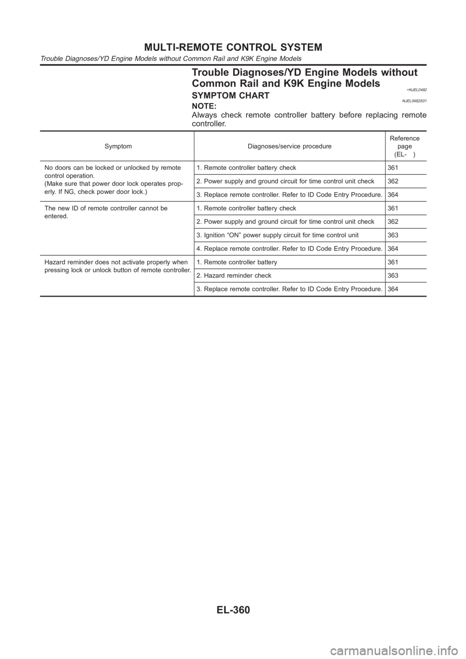
Trouble Diagnoses/YD Engine Models without
Common Rail and K9K Engine Models
=NJEL0482SYMPTOM CHARTNJEL0482S01NOTE:
Always check remote controller battery before replacing remote
controller.
Symptom Diagnoses/service procedureReference
page
(EL- )
No doors can be locked or unlocked by remote
control operation.
(Make sure that power door lock operates prop-
erly. If NG, check power door lock.)1. Remote controller battery check 361
2. Power supply and ground circuit for time control unit check 362
3. Replace remote controller. Refer to ID Code Entry Procedure. 364
The new ID of remote controller cannot be
entered.1. Remote controller battery check 361
2. Power supply and ground circuit for time control unit check 362
3. Ignition “ON” power supply circuit for time control unit 363
4. Replace remote controller. Refer to ID Code Entry Procedure. 364
Hazard reminder does not activate properly when
pressing lock or unlock button of remote controller.1. Remote controller battery 361
2. Hazard reminder check 363
3. Replace remote controller. Refer to ID Code Entry Procedure. 364
MULTI-REMOTE CONTROL SYSTEM
Trouble Diagnoses/YD Engine Models without Common Rail and K9K Engine Models
EL-360
Page 2698 of 3189
POWER SUPPLY AND GROUND CIRCUIT CHECK=NJEL0482S03
1 CHECK MAIN POWER SUPPLY CIRCUIT FOR TIME CONTROL UNIT
1. Disconnect time control unit harness connector.
2. Check voltage between time control unit harness connector terminal 9 and ground.
SEL487X
Refer to wiring diagram in EL-353.
OK or NG
OK GO TO 2.
NGCheck the following.
15A fuse [No. 5, located in fuse block (J/B)]
Harness for open or short between time control unit and fuse
2 CHECK GROUND CIRCUIT FOR TIME CONTROL UNIT
Check continuity between time control unit harness connector terminal 16and ground.
SEL448X
Refer to wiring diagram in EL-353.
OK or NG
OK Power supply and ground circuits are OK.
NG Check ground harness.
MULTI-REMOTE CONTROL SYSTEM
Trouble Diagnoses/YD Engine Models without Common Rail and K9K Engine Models (Cont’d)
EL-362
Page 2699 of 3189

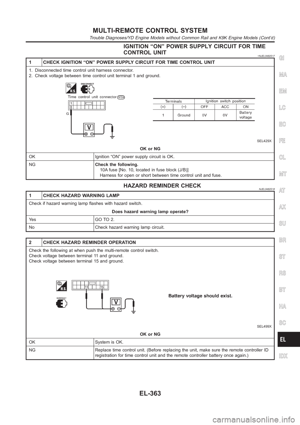
IGNITION “ON” POWER SUPPLY CIRCUIT FOR TIME
CONTROL UNIT
=NJEL0482S17
1 CHECK IGNITION “ON” POWER SUPPLY CIRCUIT FOR TIME CONTROL UNIT
1. Disconnected time control unit harness connector.
2. Check voltage between time control unit terminal 1 and ground.
SEL429X
OK or NG
OK Ignition “ON” power supply circuit is OK.
NGCheck the following.
10A fuse [No. 10, located in fuse block (J/B)]
Harness for open or short between time control unit and fuse.
HAZARD REMINDER CHECKNJEL0482S18
1 CHECK HAZARD WARNING LAMP
Check if hazard warning lamp flashes with hazard switch.
Does hazard warning lamp operate?
Ye s G O T O 2 .
No Check hazard warning lamp circuit.
2 CHECK HAZARD REMINDER OPERATION
Check the following at when push the multi-remote control switch.
Check voltage between terminal 11 and ground.
Check voltage between terminal 15 and ground.
SEL499X
OK or NG
OK System is OK.
NG Replace time control unit. (Before replacing the unit, make sure the remote controller ID
registration for time control unit and the remote controller battery onceagain.)
GI
MA
EM
LC
EC
FE
CL
MT
AT
AX
SU
BR
ST
RS
BT
HA
SC
IDX
MULTI-REMOTE CONTROL SYSTEM
Trouble Diagnoses/YD Engine Models without Common Rail and K9K Engine Models (Cont’d)
EL-363