Page 2493 of 3189
3 CHECK DRIVER SIDE DOOR SWITCH
Check continuity between terminals 2 and 3.
SEL325WA
OK or NG
OKCheck the following.
Driver side door switch ground circuit and condition
Harness for open or short between time control unit and driver side door switch
NG Replace driver side door switch.
GI
MA
EM
LC
EC
FE
CL
MT
AT
AX
SU
BR
ST
RS
BT
HA
SC
IDX
WARNING CHIME
Trouble Diagnoses/YD Engine Models without Common Rail and K9K Engine Models (Cont’d)
EL-157
Page 2516 of 3189
POWER SUPPLY AND GROUND CIRCUIT INSPECTION=NJEL0553S04
1 CHECK FUSE INSPECTION
Check the following.
MTBL1443
OK or NG
OK GO TO 2.
NG Replace fuse.
2 CHECK POWER SUPPLY AND IGNITION INPUT SIGNAL
Check voltage between smart entrance control unit connector M194, M195 terminals 29 and 56 and ground.
MIIA0083E
MTBL1444
OK or NG
OK GO TO 3.
NGCheck the following.
Harness for open or short between smart entrance control unit and fuse
REAR WINDOW DEFOGGER
Trouble Diagnoses/QG and YD Engine Models with Common Rail (Cont’d)
EL-180
Page 2517 of 3189
3 CHECK CONTROL UNIT GROUND CIRCUIT
Check continuity between smart entrance control unit connector M195 terminal 53 and ground.
MIIA0084E
MTBL1445
OK or NG
OK GO TO 4.
NG Repair or replace harness.
GI
MA
EM
LC
EC
FE
CL
MT
AT
AX
SU
BR
ST
RS
BT
HA
SC
IDX
REAR WINDOW DEFOGGER
Trouble Diagnoses/QG and YD Engine Models with Common Rail (Cont’d)
EL-181
Page 2522 of 3189

Trouble Diagnoses/YD Engine Models without
Common Rail and K9K Engine Models
=NJEL0465DIAGNOSTIC PROCEDURENJEL0465S01SYMPTOM: Rear window defogger does not activate, or does
not go off after activating.
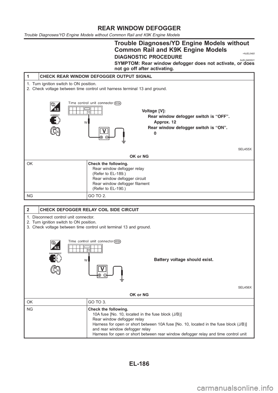
1 CHECK REAR WINDOW DEFOGGER OUTPUT SIGNAL
1. Turn ignition switch to ON position.
2. Check voltage between time control unit harness terminal 13 and ground.
SEL455X
OK or NG
OKCheck the following.
Rear window defogger relay
(Refer to EL-189.)
Rear window defogger circuit
Rear window defogger filament
(Refer to EL-190.)
NG GO TO 2.
2 CHECK DEFOGGER RELAY COIL SIDE CIRCUIT
1. Disconnect control unit connector.
2. Turn ignition switch to ON position.
3. Check voltage between time control unit terminal 13 and ground.
SEL456X
OK or NG
OK GO TO 3.
NGCheck the following.
10A fuse [No. 10, located in the fuse block (J/B)]
Rear window defogger relay
Harness for open or short between 10A fuse [No. 10, located in the fuse block(J/B)]
and rear window defogger relay
Harness for open or short between rear window defogger relay and time control unit
REAR WINDOW DEFOGGER
Trouble Diagnoses/YD Engine Models without Common Rail and K9K Engine Models
EL-186
Page 2523 of 3189
3 CHECK REAR WINDOW DEFOGGER SWITCH INPUT SIGNAL
Check continuity between time control unit terminal 3 and ground.
SEL457X
OK or NG
OK GO TO 4.
NGCheck the following.
Rear window defogger switch
(Refer to EL-189.)
Harness for open or short between time control unit and rear window defogger switch
Rear window defogger switch ground circuit
4 CHECK POWER SUPPLY AND IGNITION INPUT SIGNAL
Check voltage between time control unit terminals 1 or 9 and ground.
SEL447X
OK or NG
OK GO TO 5.
NGCheck the following.
10A fuse or 15A fuse [No. 10 or No. 5, located in the fuse block (J/B)]
Harness for open or short between time control unit and fuse
GI
MA
EM
LC
EC
FE
CL
MT
AT
AX
SU
BR
ST
RS
BT
HA
SC
IDX
REAR WINDOW DEFOGGER
Trouble Diagnoses/YD Engine Models without Common Rail and K9K Engine Models (Cont’d)
EL-187
Page 2524 of 3189
5 CHECK CONTROL UNIT GROUND CIRCUIT
Check continuity between time control unit terminal 16 and ground.
SEL448X
Yes Replace time control unit.
No Repair harness or connectors.
REAR WINDOW DEFOGGER
Trouble Diagnoses/YD Engine Models without Common Rail and K9K Engine Models (Cont’d)
EL-188
Page 2559 of 3189

YEL828D
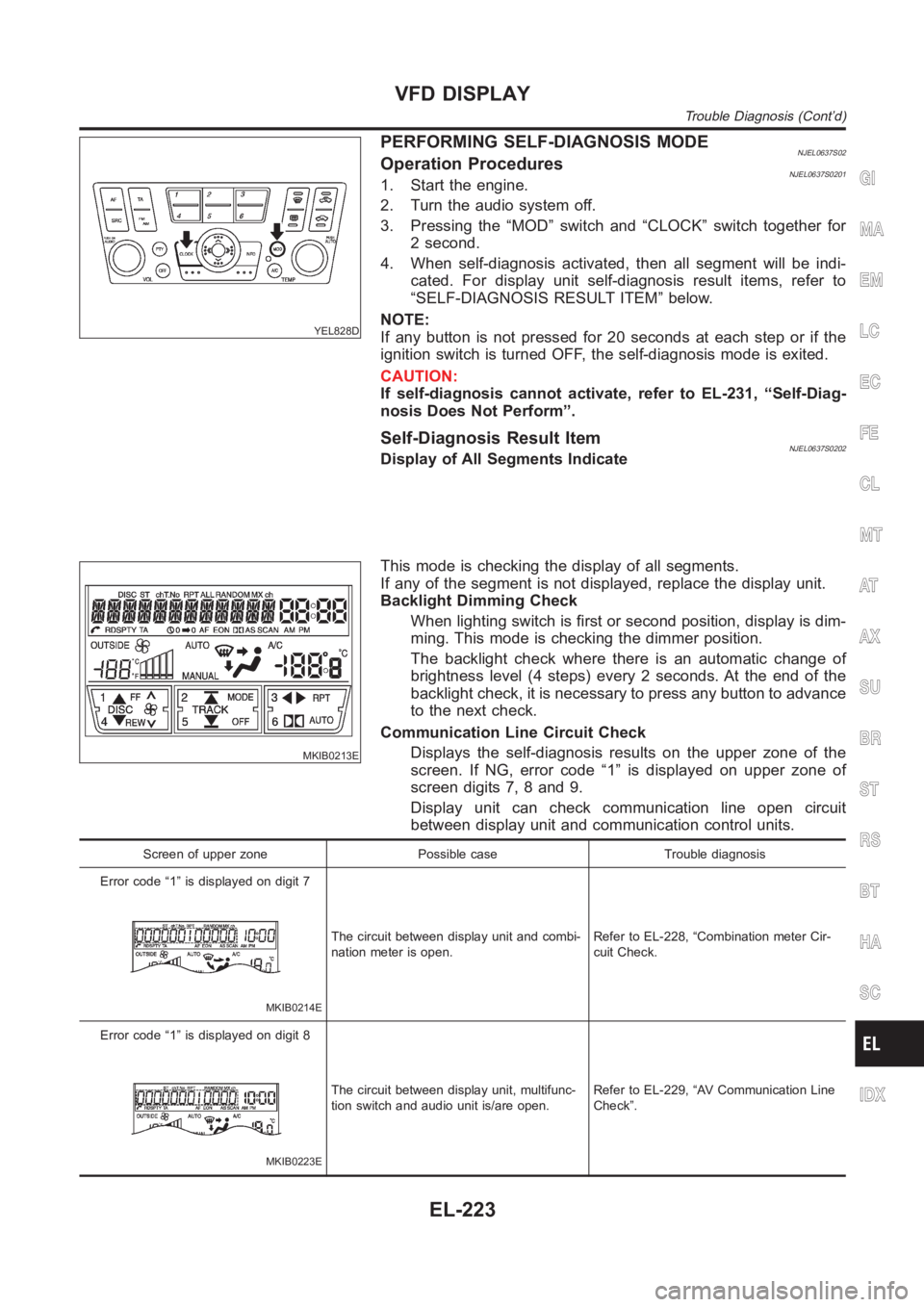
PERFORMING SELF-DIAGNOSIS MODENJEL0637S02Operation ProceduresNJEL0637S02011. Start the engine.
2. Turn the audio system off.
3. Pressing the “MOD” switch and “CLOCK” switch together for
2 second.
4. When self-diagnosis activated, then all segment will be indi-
cated. For display unit self-diagnosis result items, refer to
“SELF-DIAGNOSIS RESULT ITEM” below.
NOTE:
If any button is not pressed for 20 seconds at each step or if the
ignition switch is turned OFF, the self-diagnosis mode is exited.
CAUTION:
If self-diagnosis cannot activate, refer to EL-231, “Self-Diag-
nosis Does Not Perform”.
Self-Diagnosis Result ItemNJEL0637S0202Display of All Segments Indicate
MKIB0213E
This mode is checking the display of all segments.
If any of the segment is not displayed, replace the display unit.
Backlight Dimming Check
When lighting switch is first or second position, display is dim-
ming. This mode is checking the dimmer position.
The backlight check where there is an automatic change of
brightness level (4 steps) every 2 seconds. At the end of the
backlight check, it is necessary to press any button to advance
to the next check.
Communication Line Circuit Check
Displays the self-diagnosis results on the upper zone of the
screen. If NG, error code “1” is displayed on upper zone of
screen digits 7, 8 and 9.
Display unit can check communication line open circuit
between display unit and communication control units.
Screen of upper zone Possible case Trouble diagnosis
Error code “1” is displayed on digit 7
MKIB0214E
The circuit between display unit and combi-
nation meter is open.Refer to EL-228, “Combination meter Cir-
cuit Check.
Error code “1” is displayed on digit 8
MKIB0223E
The circuit between display unit, multifunc-
tion switch and audio unit is/are open.Refer to EL-229, “AV Communication Line
Check”.
GI
MA
EM
LC
EC
FE
CL
MT
AT
AX
SU
BR
ST
RS
BT
HA
SC
IDX
VFD DISPLAY
Trouble Diagnosis (Cont’d)
EL-223
Page 2609 of 3189

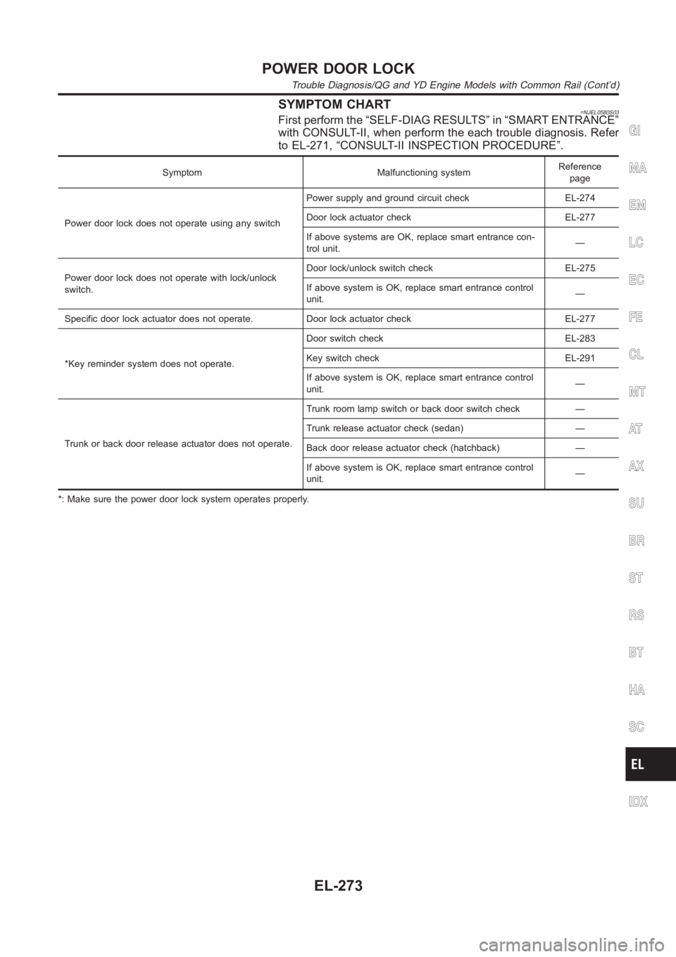
SYMPTOM CHART=NJEL0580S03First perform the “SELF-DIAG RESULTS” in “SMART ENTRANCE”
with CONSULT-II, when perform the each trouble diagnosis. Refer
to EL-271, “CONSULT-II INSPECTION PROCEDURE”.
Symptom Malfunctioning systemReference
page
Power door lock does not operate using any switchPower supply and ground circuit check EL-274
Door lock actuator check EL-277
If above systems are OK, replace smart entrance con-
trol unit.—
Power door lock does not operate with lock/unlock
switch.Door lock/unlock switch check EL-275
If above system is OK, replace smart entrance control
unit.—
Specific door lock actuator does not operate. Door lock actuator check EL-277
*Key reminder system does not operate.Door switch check EL-283
Key switch check EL-291
If above system is OK, replace smart entrance control
unit.—
Trunk or back door release actuator does not operate.Trunk room lamp switch or back door switch check —
Trunk release actuator check (sedan) —
Back door release actuator check (hatchback) —
If above system is OK, replace smart entrance control
unit.—
*: Make sure the power door lock system operates properly.
GI
MA
EM
LC
EC
FE
CL
MT
AT
AX
SU
BR
ST
RS
BT
HA
SC
IDX
POWER DOOR LOCK
Trouble Diagnosis/QG and YD Engine Models with Common Rail (Cont’d)
EL-273