2003 NISSAN ALMERA N16 Engine control circuit
[x] Cancel search: Engine control circuitPage 1851 of 3189
![NISSAN ALMERA N16 2003 Electronic Repair Manual CAN COMMUNICATION LINE
AT-395
[ALL]
D
E
F
G
H
I
J
K
L
MA
B
AT
CAN COMMUNICATION LINEPFP:31940
DescriptionECS007SN
CAN (Controller Area Network) is a serial communication line for real time application NISSAN ALMERA N16 2003 Electronic Repair Manual CAN COMMUNICATION LINE
AT-395
[ALL]
D
E
F
G
H
I
J
K
L
MA
B
AT
CAN COMMUNICATION LINEPFP:31940
DescriptionECS007SN
CAN (Controller Area Network) is a serial communication line for real time application](/manual-img/5/57350/w960_57350-1850.png)
CAN COMMUNICATION LINE
AT-395
[ALL]
D
E
F
G
H
I
J
K
L
MA
B
AT
CAN COMMUNICATION LINEPFP:31940
DescriptionECS007SN
CAN (Controller Area Network) is a serial communication line for real time application. It is an on-vehicle mul-
tiplex communication line with high data communication speed and excellent error detection ability. Many elec-
tronic control units are equipped onto a vehicle, and each control unit shares information and links with other
control units during operation (not independent). In CAN communication, control units are connected with 2
communication lines (CAN H line, CAN L line) allowing a high rate of information transmission with less wiring.
Each control unit transmits/receives data but selectively reads required data only.
TCM TERMINALS AND REFERENCE VALUE
Remarks: Specification data are reference values.
*: This terminal is connected to the ECM.
On Board Diagnosis LogicECS007SO
**: A/T COMM LINE means CAN communication line.
Self-Diagnosis Code Confirmation ProcedureECS007SP
After the repair, perform the following procedure to confirm the malfunction is eliminated.
WITH CONSULT-II
1. Turn ignition switch “ON”.
2. Select “DATA MONITOR” mode for “A/T” with CONSULT-II.
3. Wait at least 6 seconds or start engine and wait for at least 6
seconds.
4. If DTC is detected, go to AT- 3 9 7 , "
Diagnostic Procedure" .
WITHOUT CONSULT-II
1. Turn ignition switch “ON”.
2. Wait at least 6 seconds or start engine and wait at least 6 sec-
onds.
3. Perform self-diagnosis.
Refer to AT-250, "
Diagnostic Procedure Without CONSULT-II" .
4. If DTC is detected, go to AT- 3 9 7 , "
Diagnostic Procedure" .
Termi-
nal No.Wire color Item ConditionJudgement
standard
(Approx.)
5 L CAN (H) — — —
6 R CAN (L) — — —
Diagnostic trouble code Malfunction is detected when... Check items (Possible cause)
: A/T COMM LINE**
The ECM-AT communication line is open
or shorted.
●Harness or connectors
(The solenoid circuit is open or shorted.)
●Line pressure solenoid valve
: 11th judgement flicker
SAT014K
SCIA0705E
Page 1982 of 3189
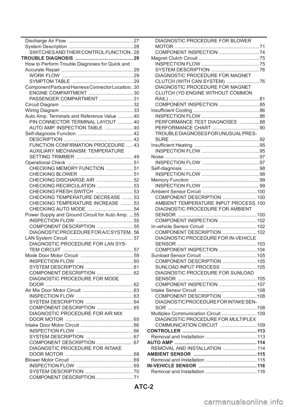
ATC-2
Discharge Air Flow ................................................. 27
System Description ................................................. 28
SWITCHES AND THEIR CONTROL FUNCTION ... 28
TROUBLE DIAGNOSIS ............................................ 29
How to Perform Trouble Diagnoses for Quick and
Accurate Repair ...................................................... 29
WORK FLOW ...................................................... 29
SYMPTOM TABLE .............................................. 29
Component Parts and Harness Connector Location ... 30
ENGINE COMPARTMENT .................................. 30
PASSENGER COMPARTMENT .......................... 31
Circuit Diagram ....................................................... 32
Wiring Diagram ....................................................... 33
Auto Amp. Terminals and Reference Value ............ 40
PIN CONNECTOR TERMINAL LAYOUT ............ 40
AUTO AMP. INSPECTION TABLE ...................... 40
Self-diagnosis Function .......................................... 42
DESCRIPTION .................................................... 42
FUNCTION CONFIRMATION PROCEDURE ...... 43
AUXILIARY MECHANISM: TEMPERATURE
SETTING TRIMMER ........................................... 49
Operational Check .................................................. 51
CHECKING MEMORY FUNCTION ..................... 51
CHECKING BLOWER ......................................... 51
CHECKING DISCHARGE AIR ............................ 52
CHECKING RECIRCULATION ............................ 53
CHECKING FRESH SWITCH ............................. 53
CHECKING TEMPERATURE DECREASE ......... 53
CHECKING TEMPERATURE INCREASE .......... 53
CHECKING AUTO MODE ................................... 54
Power Supply and Ground Circuit for Auto Amp. ... 55
INSPECTION FLOW ........................................... 55
COMPONENT DESCRIPTION ............................ 55
DIAGNOSTIC PROCEDURE FOR A/C SYSTEM ... 56
LAN System Circuit ............................................. ... 57
DIAGNOSTIC PROCEDURE FOR LAN SYS-
TEM CIRCUIT ..................................................... 57
Mode Door Motor Circuit ........................................ 59
INSPECTION FLOW ........................................... 60
SYSTEM DESCRIPTION .................................... 61
COMPONENT DESCRIPTION ............................ 62
DIAGNOSTIC PROCEDURE FOR MODE
DOOR .................................................................. 62
Air Mix Door Motor Circuit ...................................... 63
INSPECTION FLOW ........................................... 63
SYSTEM DESCRIPTION .................................... 64
COMPONENT DESCRIPTION ............................ 65
DIAGNOSTIC PROCEDURE FOR AIR MIX
DOOR MOTOR ................................................... 65
Intake Door Motor Circuit ........................................ 66
INSPECTION FLOW ........................................... 66
SYSTEM DESCRIPTION .................................
... 67
COMPONENT DESCRIPTION ............................ 67
DIAGNOSTIC PROCEDURE FOR INTAKE
DOOR MOTOR ................................................... 68
Blower Motor Circuit ............................................... 69
INSPECTION FLOW ........................................... 69
SYSTEM DESCRIPTION .................................... 70
COMPONENT DESCRIPTION ............................ 71DIAGNOSTIC PROCEDURE FOR BLOWER
MOTOR ................................................................ 71
COMPONENT INSPECTION ............................... 74
Magnet Clutch Circuit .............................................. 75
INSPECTION FLOW ............................................ 75
SYSTEM DESCRIPTION ..................................... 76
DIAGNOSTIC PROCEDURE FOR MAGNET
CLUTCH (WITH CAN SYSTEM) ......................... 76
DIAGNOSTIC PROCEDURE FOR MAGNET
CLUTCH (YD ENGINE WITHOUT COMMON
RAIL) .................................................................... 81
COMPONENT INSPECTION ............................... 85
Insufficient Cooling .................................................. 86
INSPECTION FLOW ............................................ 86
PERFORMANCE TEST DIAGNOSES ................ 88
PERFORMANCE CHART .................................... 90
TROUBLE DIAGNOSES FOR UNUSUAL PRES-
SURE ................................................................... 92
Insufficient Heating ................................................. 95
INSPECTION FLOW ............................................ 95
Noise ....................................................................... 97
INSPECTION FLOW ............................................ 97
Self-diagnosis ......................................................... 98
INSPECTION FLOW ............................................ 98
Memory Function .................................................... 99
INSPECTION FLOW ............................................ 99
Ambient Sensor Circuit .........................................100
COMPONENT DESCRIPTION ..........................100
AMBIENT TEMPERATURE INPUT PROCESS .100
DIAGNOSTIC PROCEDURE FOR AMBIENT
SENSOR ............................................................100
COMPONENT INSPECTION .............................102
In-vehicle Sensor Circuit .......................................102
COMPONENT DESCRIPTION ..........................102
DIAGNOSTIC PROCEDURE FOR IN-VEHICLE
SENSOR ............................................................103
COMPONENT INSPECTION .............................104
Sunload Sensor Circuit .........................................105
COMPONENT DESCRIPTION ..........................105
SUNLOAD INPUT PROCESS ...........................105
DIAGNOSTIC PROCEDURE FOR SUNLOAD
SENSOR ............................................................105
COMPONENT INSPECTION .............................107
Intake Sensor Circuit .............................................108
COMPONENT DESCRIPTION ..........................108
DIAGNOSTIC PROCEDURE FOR INTAKE SEN-
SOR ...................................................................108
Multiplex Communication Circuit ...........................109
DIAGNOSTIC PROCEDURE FOR MULTIPLEX
COMMUNICATION CIRCUIT ............................109
CONTROLLER ........................................................113
Removal and Installation .......................................113
AUTO AMP ..............................................................114
REMOVAL AND INSTALLATION ..........................114
AMBIENT SENSOR ................................................115
Removal and Installation .......................................115
IN-VEHICLE SENSOR ............................................116
Removal and Installation .......................................116
Page 1983 of 3189
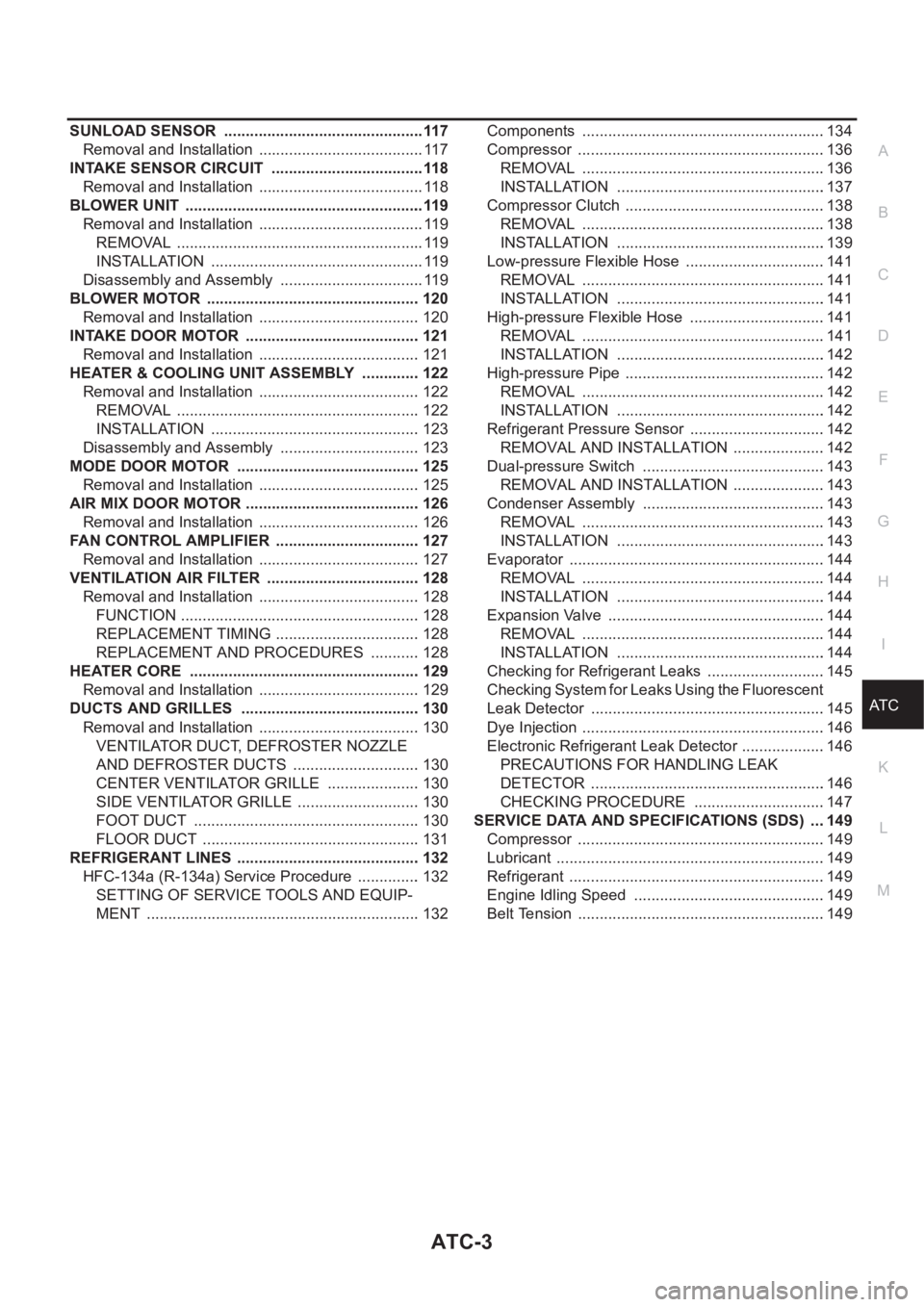
ATC-3
C
D
E
F
G
H
I
K
L
MA
B
AT C SUNLOAD SENSOR ...............................................117
Removal and Installation ....................................... 117
INTAKE SENSOR CIRCUIT ....................................118
Removal and Installation ....................................... 118
BLOWER UNIT ........................................................119
Removal and Installation ....................................... 119
REMOVAL .......................................................... 119
INSTALLATION .................................................. 119
Disassembly and Assembly .................................. 119
BLOWER MOTOR .................................................. 120
Removal and Installation ...................................... 120
INTAKE DOOR MOTOR ......................................... 121
Removal and Installation ...................................... 121
HEATER & COOLING UNIT ASSEMBLY .............. 122
Removal and Installation ...................................... 122
REMOVAL ......................................................... 122
INSTALLATION ................................................. 123
Disassembly and Assembly ................................. 123
MODE DOOR MOTOR ........................................... 125
Removal and Installation ...................................... 125
AIR MIX DOOR MOTOR ......................................... 126
Removal and Installation ...................................... 126
FAN CONTROL AMPLIFIER .................................. 127
Removal and Installation ...................................... 127
VENTILATION AIR FILTER .................................... 128
Removal and Installation ...................................... 128
FUNCTION ........................................................ 128
REPLACEMENT TIMING .................................. 128
REPLACEMENT AND PROCEDURES ............ 128
HEATER CORE ...................................................... 129
Removal and Installation ...................................... 129
DUCTS AND GRILLES .......................................... 130
Removal and Installation ...................................... 130
VENTILATOR DUCT, DEFROSTER NOZZLE
AND DEFROSTER DUCTS .............................. 130
CENTER VENTILATOR GRILLE ...................... 130
SIDE VENTILATOR GRILLE ............................. 130
FOOT DUCT ..................................................... 130
FLOOR DUCT ................................................... 131
REFRIGERANT LINES ........................................... 132
HFC-134a (R-134a) Service Procedure ............... 132
SETTING OF SERVICE TOOLS AND EQUIP-
MENT ................................................................ 132Components .........................................................134
Compressor ..........................................................136
REMOVAL .........................................................136
INSTALLATION .................................................137
Compressor Clutch .............................................. .138
REMOVAL .........................................................138
INSTALLATION .................................................139
Low-pressure Flexible Hose .................................141
REMOVAL .........................................................141
INSTALLATION .................................................141
High-pressure Flexible Hose ................................141
REMOVAL .........................................................141
INSTALLATION .................................................142
High-pressure Pipe ...............................................142
REMOVAL .........................................................142
INSTALLATION .................................................142
Refrigerant Pressure Sensor ................................142
REMOVAL AND INSTALLATION ......................142
Dual-pressure Switch ...........................................143
REMOVAL AND INSTALLATION ......................143
Condenser Assembly ...........................................143
REMOVAL .........................................................143
INSTALLATION .................................................143
Evaporator ............................................................144
REMOVAL .........................................................144
INSTALLATION .................................................144
Expansion Valve ...................................................144
REMOVAL .........................................................144
INSTALLATION .................................................144
Checking for Refrigerant Leaks ............................145
Checking System for Leaks Using the Fluorescent
Leak Detector .......................................................145
Dye Injection .........................................................146
Electronic Refrigerant Leak Detector ....................146
PRECAUTIONS FOR HANDLING LEAK
DETECTOR .......................................................146
CHECKING PROCEDURE ...............................147
SERVICE DATA AND SPECIFICATIONS (SDS) ....149
Compressor ..........................................................149
Lubricant ...............................................................149
Refrigerant ............................................................149
Engine Idling Speed .............................................149
Belt Tension ..........................................................149
Page 2050 of 3189
ATC-70
TROUBLE DIAGNOSIS
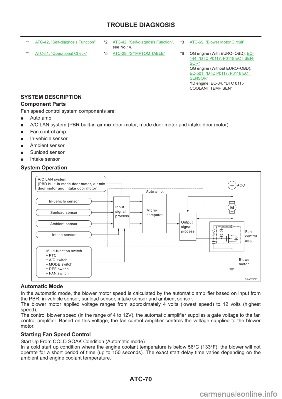
SYSTEM DESCRIPTION
Component Parts
Fan speed control system components are:
●Auto amp.
●A/C LAN system (PBR built-in air mix door motor, mode door motor and intake door motor)
●Fan control amp.
●In-vehicle sensor
●Ambient sensor
●Sunload sensor
●Intake sensor
System Operation
Automatic Mode
In the automatic mode, the blower motor speed is calculated by the automatic amplifier based on input from
the PBR, in-vehicle sensor, sunload sensor, intake sensor and ambient sensor.
The blower motor applied voltage ranges from approximately 4 volts (lowest speed) to 12 volts (highest
speed).
The control blower speed (in the range of 4 to 12V), the automatic amplifier supplies a gate voltage to the fan
control amplifier. Based on this voltage, the fan control amplifier controls the voltage supplied to the blower
motor.
Starting Fan Speed Control
Start Up From COLD SOAK Condition (Automatic mode)
In a cold start up condition where the engine coolant temperature is below 56°C (133°F), the blower will not
operate for a short period of time (up to 150 seconds). The exact start delay time varies depending on the
ambient and engine coolant temperature.
*1AT C - 4 2 , "Self-diagnosis Function"*2AT C - 4 2 , "Self-diagnosis Function",
see No.14.*3AT C - 6 9 , "Blower Motor Circuit"
*4AT C - 5 1 , "Operational Check"*5AT C - 2 9 , "SYMPTOM TABLE"*6 QG engine (With EURO–OBD): EC-
144, "DTC P0117, P0118 ECT SEN-
SOR"
QG engine (Without EURO–OBD):
EC-501, "
DTC P0117, P0118 ECT
SENSOR"
YD engine: EC-84, "DTC 0115
COOLANT TEMP SEN"
RJIA0785E
Page 2239 of 3189
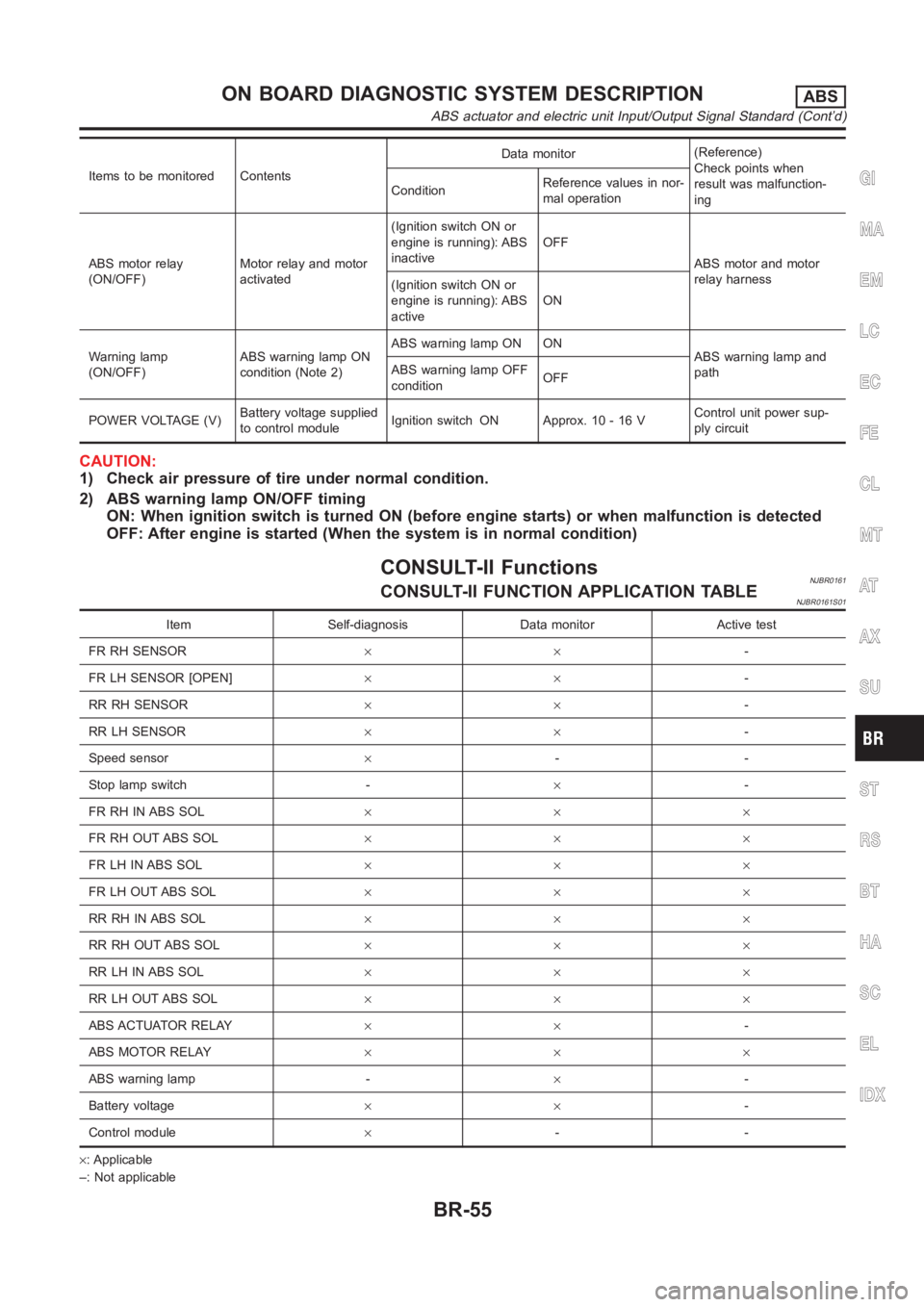
Items to be monitored ContentsData monitor(Reference)
Check points when
result was malfunction-
ing ConditionReference values in nor-
mal operation
ABS motor relay
(ON/OFF)Motor relay and motor
activated(Ignition switch ON or
engine is running): ABS
inactiveOFF
ABS motor and motor
relay harness
(Ignition switch ON or
engine is running): ABS
activeON
Warning lamp
(ON/OFF)ABS warning lamp ON
condition (Note 2)ABS warning lamp ON ON
ABS warning lamp and
path ABS warning lamp OFF
conditionOFF
POWER VOLTAGE (V)Battery voltage supplied
to control moduleIgnition switch ON Approx. 10 - 16 VControl unit power sup-
ply circuit
CAUTION:
1) Check air pressure of tire under normal condition.
2) ABS warning lamp ON/OFF timing
ON: When ignition switch is turned ON (before engine starts) or when malfunction is detected
OFF: After engine is started (When the system is in normal condition)
CONSULT-II FunctionsNJBR0161CONSULT-II FUNCTION APPLICATION TABLENJBR0161S01
Item Self-diagnosis Data monitor Active test
FR RH SENSOR××-
FR LH SENSOR [OPEN]××-
RR RH SENSOR××-
RR LH SENSOR××-
Speed sensor×--
Stop lamp switch -×-
FR RH IN ABS SOL×××
FR RH OUT ABS SOL×××
FR LH IN ABS SOL×××
FR LH OUT ABS SOL×××
RR RH IN ABS SOL×××
RR RH OUT ABS SOL×××
RR LH IN ABS SOL×××
RR LH OUT ABS SOL×××
ABS ACTUATOR RELAY××-
ABS MOTOR RELAY×××
ABS warning lamp -×-
Battery voltage××-
Control module×--
×: Applicable
–: Not applicable
GI
MA
EM
LC
EC
FE
CL
MT
AT
AX
SU
ST
RS
BT
HA
SC
EL
IDX
ON BOARD DIAGNOSTIC SYSTEM DESCRIPTIONABS
ABS actuator and electric unit Input/Output Signal Standard (Cont’d)
BR-55
Page 2339 of 3189
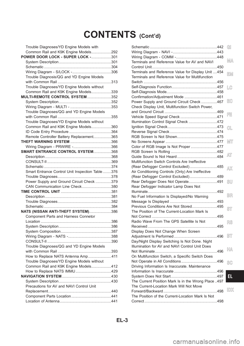
Trouble Diagnoses/YD Engine Models with
Common Rail and K9K Engine Models...................292
POWER DOOR LOCK - SUPER LOCK -...................301
System Description ..................................................301
Schematic <0011001100110011001100110011001100110011001100110011001100110011001100110011001100110011001100110011001100110011001100110011001100110011001100110011001100110011001100110011001100110011001100110011001100
11001100110011[..........304
Wiring Diagram - S/LOCK - .....................................306
Trouble Diagnosis/QG and YD Engine Models
with Common Rail ...................................................313
Trouble Diagnoses/YD Engine Models without
Common Rail and K9K Engine Models...................339
MULTI-REMOTE CONTROL SYSTEM.......................352
System Description ..................................................352
Wiring Diagram - MULTI - .......................................353
Trouble Diagnoses/QG and YD Engine Models
with Common Rail ...................................................355
Trouble Diagnoses/YD Engine Models without
Common Rail and K9K Engine Models...................360
ID Code Entry Procedure ........................................364
Remote Controller Battery Replacement.................365
THEFT WARNING SYSTEM.......................................366
Wiring Diagram - PRWIRE -....................................366
SMART ENTRANCE CONTROL SYSTEM.................368
Description <0011001100110011001100110011001100110011001100110011001100110011001100110011001100110011001100110011001100110011001100110011001100110011001100110011001100110011001100110011001100110011001100110011001100
110011[...........368
CONSULT-II <0011001100110011001100110011001100110011001100110011001100110011001100110011001100110011001100110011001100110011001100110011001100110011001100110011001100110011001100110011001100110011001100110011001100
1100110011[........369
Schematic <0011001100110011001100110011001100110011001100110011001100110011001100110011001100110011001100110011001100110011001100110011001100110011001100110011001100110011001100110011001100110011001100110011001100
11001100110011[..........374
Smart Entrance Control Unit Inspection Table ........376
Trouble Diagnoses...................................................378
Power Supply and Ground Circuit Check ...............379
CAN Communication Line Check ............................380
TIME CONTROL UNIT................................................381
Description <0011001100110011001100110011001100110011001100110011001100110011001100110011001100110011001100110011001100110011001100110011001100110011001100110011001100110011001100110011001100110011001100110011001100
110011[...........381
Trouble Diagnoses...................................................382
Schematic <0011001100110011001100110011001100110011001100110011001100110011001100110011001100110011001100110011001100110011001100110011001100110011001100110011001100110011001100110011001100110011001100110011001100
11001100110011[..........384
NATS (NISSAN ANTI-THEFT SYSTEM).....................386
Component Parts and Harness Connetor
Location <0011001100110011001100110011001100110011001100110011001100110011001100110011001100110011001100110011001100110011001100110011001100110011001100110011001100110011001100110011001100110011001100110011001100
110011001100110011[............386
System Description ..................................................386
System Composition ................................................387
Wiring Diagram - NATS -.........................................388
CONSULT-II <0011001100110011001100110011001100110011001100110011001100110011001100110011001100110011001100110011001100110011001100110011001100110011001100110011001100110011001100110011001100110011001100110011001100
1100110011[........390
Trouble Diagnoses/QG and YD Engine Models
with Common Rail ...................................................393
How to Replace NATS Antenna Amp ...................... 411
Trouble Diagnoses/YD Engine Models without
Common Rail and K9K Engine Models...................412
How to Replace NATS IMMU ..................................429
NAVIGATION SYSTEM...............................................430
System Description ..................................................430
Precautions for AV and NAVI Control Unit
Replacement <0011001100110011001100110011001100110011001100110011001100110011001100110011001100110011001100110011001100110011001100110011001100110011001100110011001100110011001100110011001100110011001100110011001100
110011[........440
Component Parts Location ......................................441
Location of Antenna .................................................441Schematic <0011001100110011001100110011001100110011001100110011001100110011001100110011001100110011001100110011001100110011001100110011001100110011001100110011001100110011001100110011001100110011001100110011001100
11001100110011[..........442
Wiring Diagram - NAVI - ..........................................443
Wiring Diagram - COMM -.......................................448
Terminals and Reference Value for AV and NAVI
Control Unit <0011001100110011001100110011001100110011001100110011001100110011001100110011001100110011001100110011001100110011001100110011001100110011001100110011001100110011001100110011001100110011001100110011001100
110011[..........450
Terminals and Reference Value for Display Unit ....454
Terminals and Reference Value for Multifunction
Switch <0011001100110011001100110011001100110011001100110011001100110011001100110011001100110011001100110011001100110011001100110011001100110011001100110011001100110011001100110011001100110011001100110011001100
11001100110011001100110011[.............456
Self-Diagnosis Function ...........................................457
Self-Diagnosis Mode................................................458
Confirmation/Adjustment Mode ...............................461
Power Supply and Ground Circuit Check ...............467
Check Display Unit, Multifunction Switch Power,
and Ground Circuit ..................................................469
Vehicle Speed Signal Check ...................................471
Illumination Control Signal Check ...........................472
Ignition Signal Check ...............................................473
Reverse Signal Check .............................................474
RGB Screen Is Not Shown......................................475
No Screens Appear .................................................477
Color of RGB Image Is Not Proper .........................477
RGB Screen Is Rolling ............................................482
Guide Sound Is Not Heard ......................................484
Multifunction Switch Controls Are Ineffective
(Rear Defogger Control Excluded) ..........................485
Air Conditioning Controls (Only) Are Ineffective
(Rear Defogger Control Excluded) ..........................489
Rear Defogger Does Not Operate...........................491
Rear Defogger Indicator Lamp Does Not
Illuminate<0011001100110011001100110011001100110011001100110011001100110011001100110011001100110011001100110011001100110011001100110011001100110011001100110011001100110011001100110011001100110011001100110011001100
1100110011[.............492
No Fuel Information Is Displayed/No Warning
Message Is Displayed .............................................493
Previous Conditions Are Not Stored........................495
The Position of The Current-Location Mark Is
Not Correct <0011001100110011001100110011001100110011001100110011001100110011001100110011001100110011001100110011001100110011001100110011001100110011001100110011001100110011001100110011001100110011001100110011001100
1100110011[.........495
Radio Wave From The GPS Satellite Is Not
Received <0011001100110011001100110011001100110011001100110011001100110011001100110011001100110011001100110011001100110011001100110011001100110011001100110011001100110011001100110011001100110011001100110011001100
110011001100110011[...........495
Display Does Not Change When Screen
Adjustment Is Performed .........................................496
Day/Night Display Switching Is Not Done. Night
Illumination for AV and NAVI Control Unit Does
Not Illuminate ...........................................................496
On Multifunction Switch, a Specific Switch Does
Not Operate in All Conditions ..................................496
Driving Information Is Inaccurate. Maintenance
Information Is Inaccurate .........................................496
System Does Not Start ............................................497
The Current Position Mark Is in the Wrong Place ..497
The Current-Location Mark Will Not Move
Forward/Backward ...................................................498
The Position of the Current-Location Mark Is Not
Correct <0011001100110011001100110011001100110011001100110011001100110011001100110011001100110011001100110011001100110011001100110011001100110011001100110011001100110011001100110011001100110011001100110011001100
1100110011001100110011[.............498
GI
MA
EM
LC
EC
FE
CL
MT
AT
AX
SU
BR
ST
RS
BT
HA
SC
IDX
CONTENTS(Cont’d)
EL-3
Page 2439 of 3189
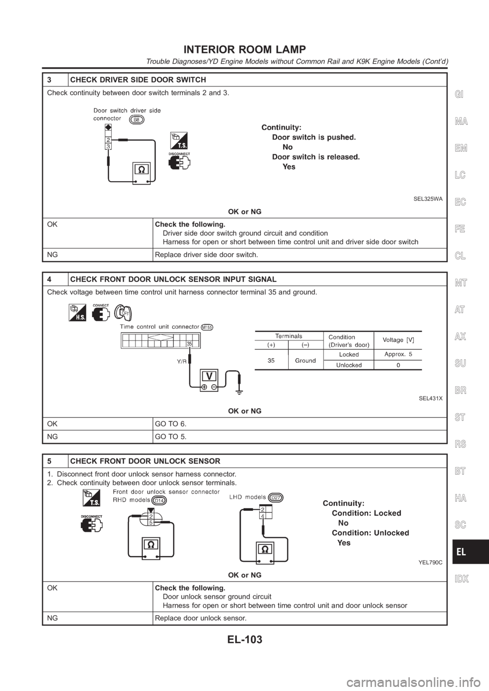
3 CHECK DRIVER SIDE DOOR SWITCH
Check continuity between door switch terminals 2 and 3.
SEL325WA
OK or NG
OKCheck the following.
Driver side door switch ground circuit and condition
Harness for open or short between time control unit and driver side door switch
NG Replace driver side door switch.
4 CHECK FRONT DOOR UNLOCK SENSOR INPUT SIGNAL
Check voltage between time control unit harness connector terminal 35 andground.
SEL431X
OK or NG
OK GO TO 6.
NG GO TO 5.
5 CHECK FRONT DOOR UNLOCK SENSOR
1. Disconnect front door unlock sensor harness connector.
2. Check continuity between door unlock sensor terminals.
YEL790C
OK or NG
OKCheck the following.
Door unlock sensor ground circuit
Harness for open or short between time control unit and door unlock sensor
NG Replace door unlock sensor.
GI
MA
EM
LC
EC
FE
CL
MT
AT
AX
SU
BR
ST
RS
BT
HA
SC
IDX
INTERIOR ROOM LAMP
Trouble Diagnoses/YD Engine Models without Common Rail and K9K Engine Models (Cont’d)
EL-103
Page 2443 of 3189
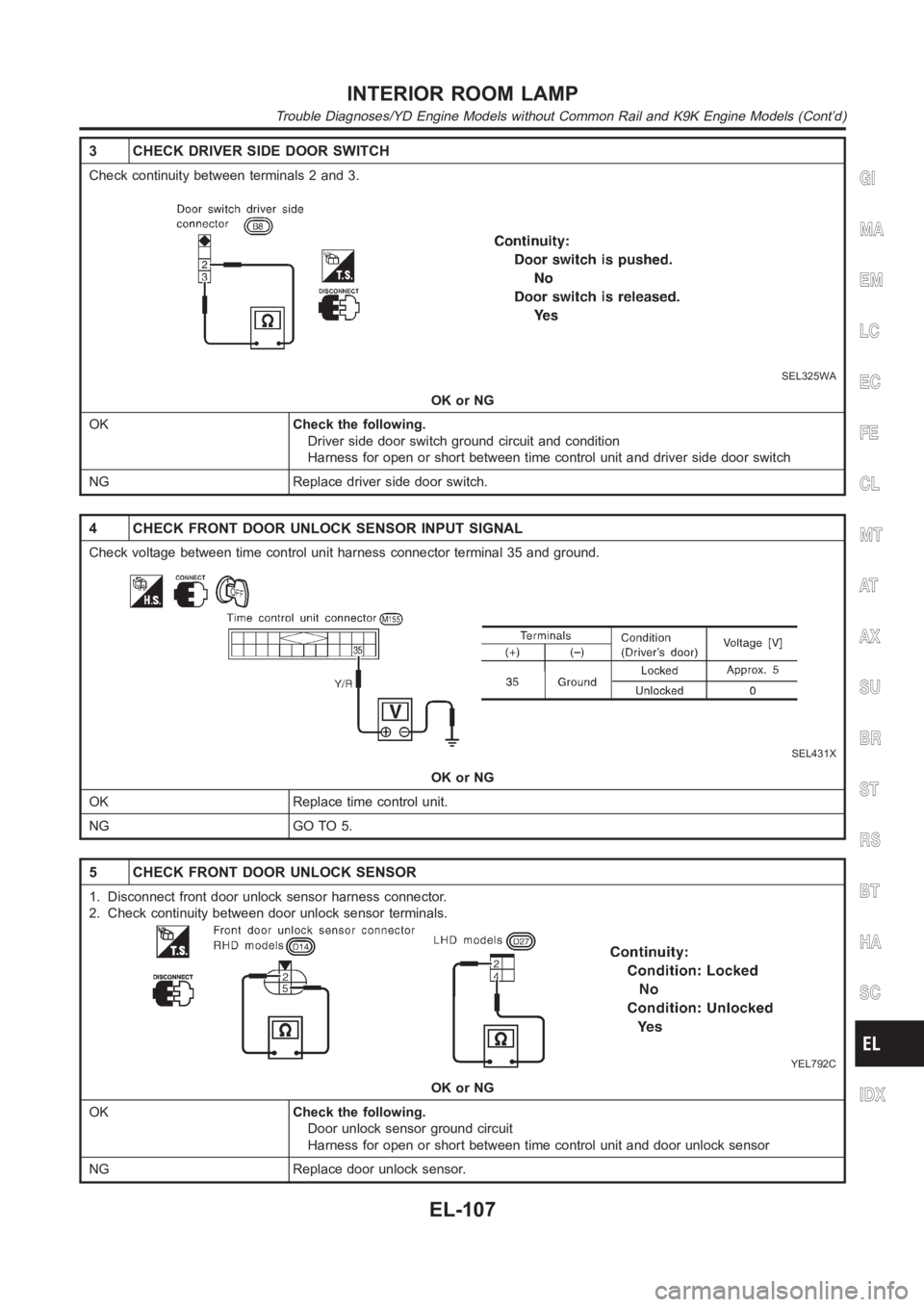
3 CHECK DRIVER SIDE DOOR SWITCH
Check continuity between terminals 2 and 3.
SEL325WA
OK or NG
OKCheck the following.
Driver side door switch ground circuit and condition
Harness for open or short between time control unit and driver side door switch
NG Replace driver side door switch.
4 CHECK FRONT DOOR UNLOCK SENSOR INPUT SIGNAL
Check voltage between time control unit harness connector terminal 35 andground.
SEL431X
OK or NG
OK Replace time control unit.
NG GO TO 5.
5 CHECK FRONT DOOR UNLOCK SENSOR
1. Disconnect front door unlock sensor harness connector.
2. Check continuity between door unlock sensor terminals.
YEL792C
OK or NG
OKCheck the following.
Door unlock sensor ground circuit
Harness for open or short between time control unit and door unlock sensor
NG Replace door unlock sensor.
GI
MA
EM
LC
EC
FE
CL
MT
AT
AX
SU
BR
ST
RS
BT
HA
SC
IDX
INTERIOR ROOM LAMP
Trouble Diagnoses/YD Engine Models without Common Rail and K9K Engine Models (Cont’d)
EL-107