Page 2446 of 3189

Component Parts and Harness Connector
Location
NJEL0441For details, refer to “ELECTRICAL UNIT LOCATION” (EL-543) and
“HARNESS LAYOUT” (EL-550).
System DescriptionNJEL0442UNIFIED CONTROL METERNJEL0442S01Speedometer, odo/trip meter, tachometer, fuel gauge and water temperature gauge are controlled totally
by control unit built-in combination meter.
Digital meter is adopted for odo/trip meter.*
*The record of the odo meter is kept even if the battery cable is disconnected. The record of the trip meter
is erased when the battery cable is disconnected.
Odo/trip meter segment can be checked in diagnosis mode.
Meter/gauge can be checked in diagnosis mode.
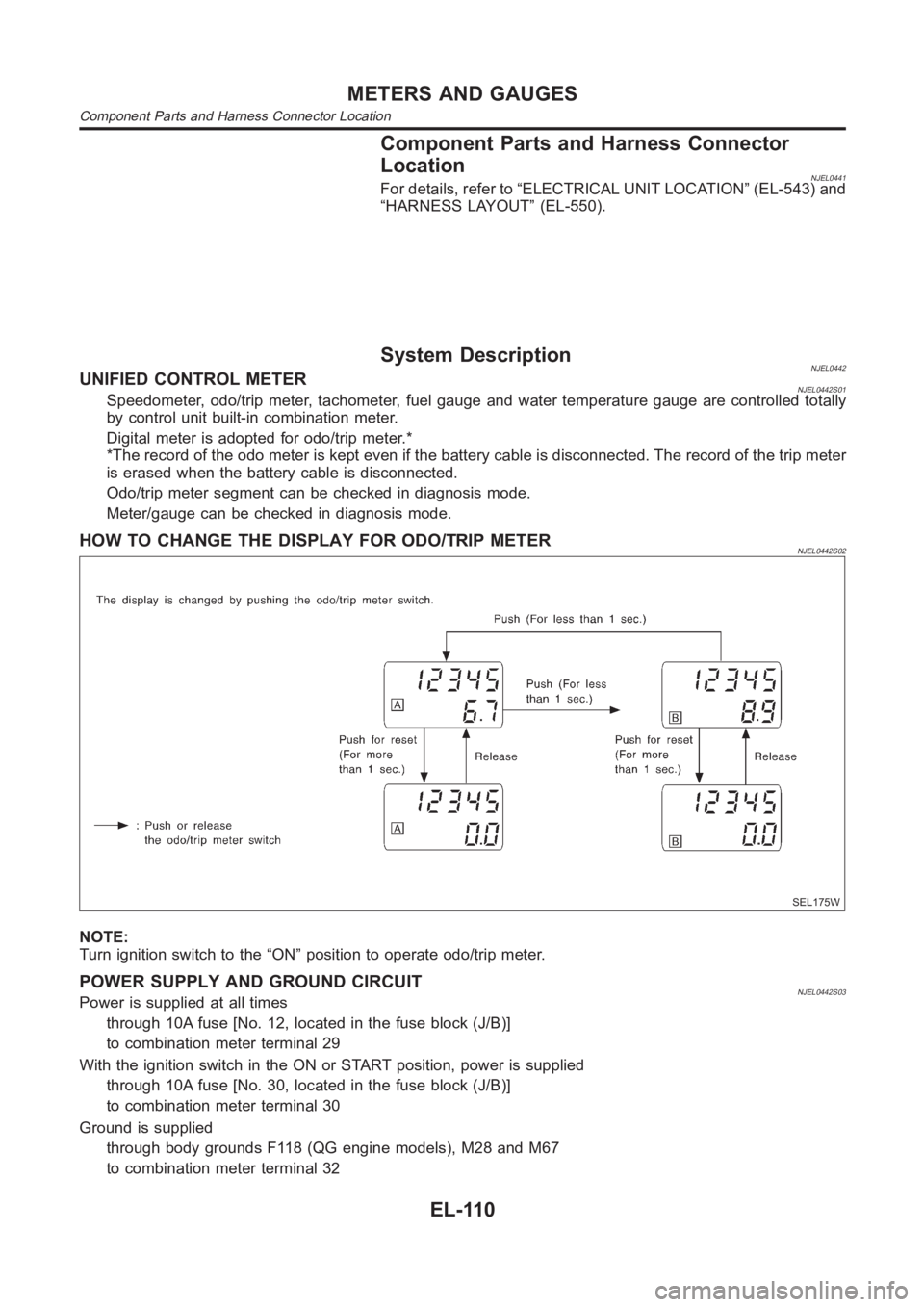
HOW TO CHANGE THE DISPLAY FOR ODO/TRIP METERNJEL0442S02
SEL175W
NOTE:
Turn ignition switch to the “ON” position to operate odo/trip meter.
POWER SUPPLY AND GROUND CIRCUITNJEL0442S03Power is supplied at all times
through 10A fuse [No. 12, located in the fuse block (J/B)]
to combination meter terminal 29
With the ignition switch in the ON or START position, power is supplied
through 10A fuse [No. 30, located in the fuse block (J/B)]
to combination meter terminal 30
Ground is supplied
through body grounds F118 (QG engine models), M28 and M67
to combination meter terminal 32
METERS AND GAUGES
Component Parts and Harness Connector Location
EL-110
Page 2460 of 3189

Models with ABS=NJEL0448S0402
1 ABS ACTUATOR AND ELECTRIC UNIT SYSTEM INSPECTION
Perform ABS actuator and electric unit self-diagnosis.
Refer to BR-55, “CONSULT-II Functions”.
OK or NG
OK GO TO 2.
NG Check ABS control system. Refer to BR-62, “TROUBLE DIAGNOSIS — BASIC INSPEC-
TION”.
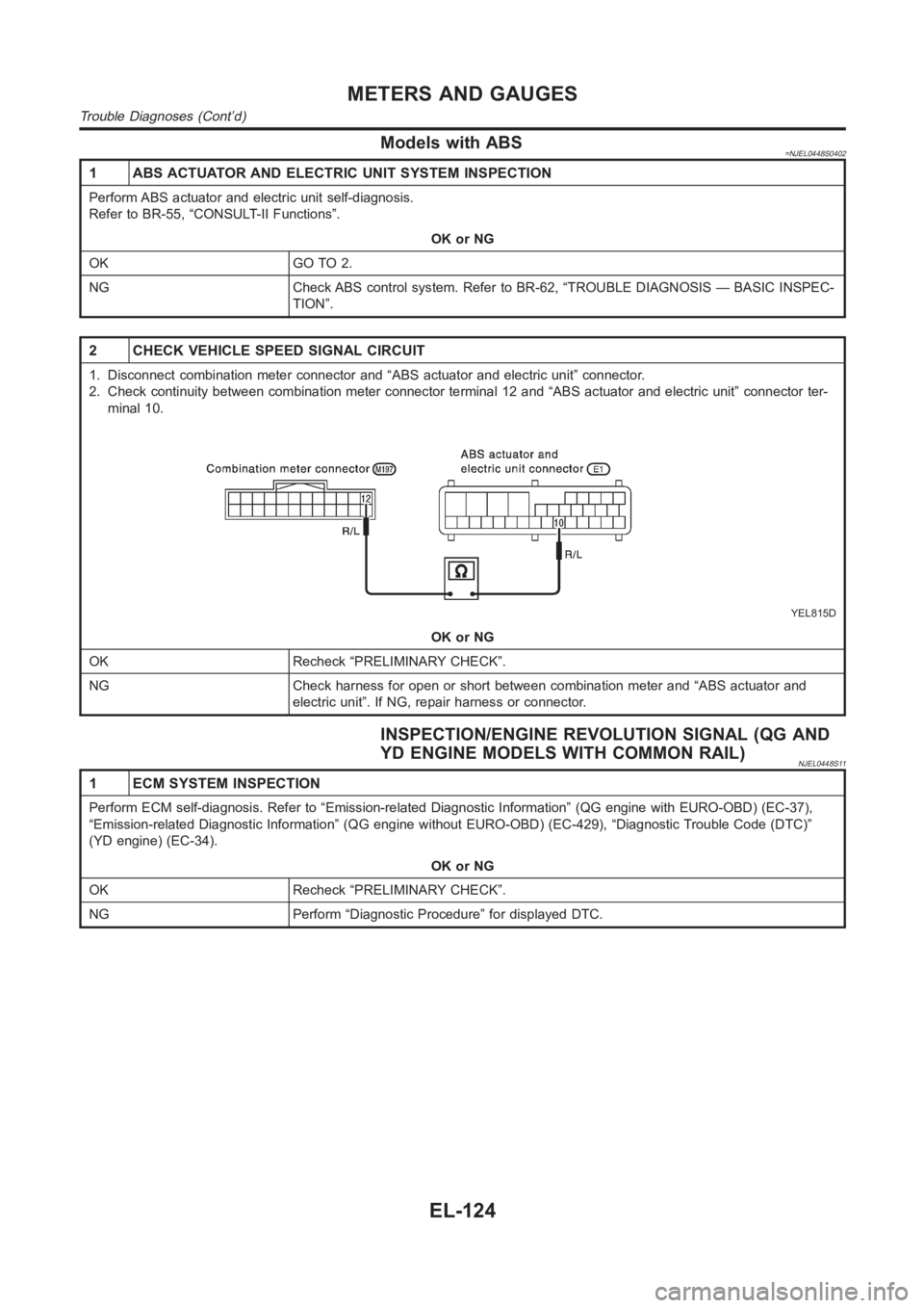
2 CHECK VEHICLE SPEED SIGNAL CIRCUIT
1. Disconnect combination meter connector and “ABS actuator and electricunit” connector.
2. Check continuity between combination meter connector terminal 12 and “ABS actuator and electric unit” connector ter-
minal 10.
YEL815D
OK or NG
OK Recheck “PRELIMINARY CHECK”.
NG Check harness for open or short between combination meter and “ABS actuator and
electric unit”. If NG, repair harness or connector.
INSPECTION/ENGINE REVOLUTION SIGNAL (QG AND
YD ENGINE MODELS WITH COMMON RAIL)
NJEL0448S11
1 ECM SYSTEM INSPECTION
Perform ECM self-diagnosis. Refer to “Emission-related Diagnostic Information” (QG engine with EURO-OBD) (EC-37),
“Emission-related Diagnostic Information” (QG engine without EURO-OBD) (EC-429), “Diagnostic Trouble Code (DTC)”
(YD engine) (EC-34).
OK or NG
OK Recheck “PRELIMINARY CHECK”.
NG Perform “Diagnostic Procedure” for displayed DTC.
METERS AND GAUGES
Trouble Diagnoses (Cont’d)
EL-124
Page 2478 of 3189
![NISSAN ALMERA N16 2003 Electronic Repair Manual 4. Select the desired part to be diagnosed on the “SELECT TES-
T ITEM” screen.
Data monitor item (KEY REMINDER)
Monitored item Description
IGNITION SW Indicates [ON/OFF] condition of ignition swit NISSAN ALMERA N16 2003 Electronic Repair Manual 4. Select the desired part to be diagnosed on the “SELECT TES-
T ITEM” screen.
Data monitor item (KEY REMINDER)
Monitored item Description
IGNITION SW Indicates [ON/OFF] condition of ignition swit](/manual-img/5/57350/w960_57350-2477.png)
4. Select the desired part to be diagnosed on the “SELECT TES-
T ITEM” screen.
Data monitor item (KEY REMINDER)
Monitored item Description
IGNITION SW Indicates [ON/OFF] condition of ignition switch.
KEY IN DETECT Indicates [ON/OFF] condition of electronic key switch.
DR DOOR SW Indicates [ON/OFF] condition of front door switch (driver side).
CDL LOCK SW Indicates [ON/OFF] condition of door lock/unlock switch.
RKE LOCK Indicates [ON/OFF] condition of lock signal from remote controller.
Data monitor item (Light warning chime)
Monitored item Description
IGN ON SW Indicates [ON/OFF] condition of ignition switch.
DR DOOR SW Indicates [ON/OFF] condition of front door switch (driver side).
TAIL LAMP ON Indicates [ON/OFF] condition of lighting switch.
SYMPTOM CHARTNJEL0551S02First perform the “SELF-DIAG RESULTS” in “SMART ENTRANCE”
with CONSULT-II, when perform the each trouble diagnosis.
Symptom Diagnoses/Service procedure Reference page
Light warning chime does not activate.Power supply and ground circuit checkEL-143, “Power Supply
and Ground Circuit
Check”
Lighting switch checkEL-144, “Lighting Switch
Input Signal Check”
Front door switch (driver side) checkEL-150, “Front Door
Switch (Driver side)
Check”
Key warning chime does not activate.Power supply and ground circuit checkEL-143, “Power Supply
and Ground Circuit
Check”
Key switch insert signal checkEL-147, “Key Switch
Insert Signal Check”
Front door switch (driver side) checkEL-150, “Front Door
Switch (Driver side)
Check”
All warning chimes do not activate. Power supply and ground circuit checkEL-143, “Power Supply
and Ground Circuit
Check”
With the ignition switch turned OFF and the
door closed (driver side) turning the lighting
switch ON (1st) activates the chime.Front door switch (driver side) checkEL-150, “Front Door
Switch (Driver side)
Check”
WARNING CHIME
Trouble Diagnoses/QG and YD Engine Models with Common Rail (Cont’d)
EL-142
Page 2479 of 3189
POWER SUPPLY AND GROUND CIRCUIT CHECKNJEL0551S03
1 POWER SUPPLY CIRCUIT CHECK
1. Disconnect smart entrance control unit connector.
2. Check the following.
MKIB0013E
MTBL1438
OK or NG
OK GO TO 2.
NGCheck the following.
10A fuse [NO. 10, located in fuse block (J/B)].
10A fuse [NO. 12, located in fuse block (J/B)].
Check harness for open or short between smart entrance control unit and fuse.
2 GROUND CIRCUIT CHECK
Check continuity between smart entrance control unit harness connector M195 terminal 53 (B) and ground.
MKIB0014E
Continuity should exist.
OK or NG
OK INSPECTION END.
NG Check ground circuit for open or short.
GI
MA
EM
LC
EC
FE
CL
MT
AT
AX
SU
BR
ST
RS
BT
HA
SC
IDX
WARNING CHIME
Trouble Diagnoses/QG and YD Engine Models with Common Rail (Cont’d)
EL-143
Page 2481 of 3189

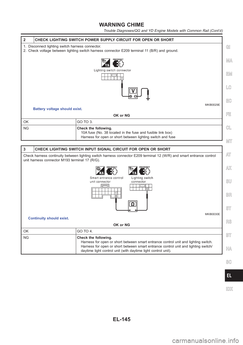
2 CHECK LIGHTING SWITCH POWER SUPPLY CIRCUIT FOR OPEN OR SHORT
1. Disconnect lighting switch harness connector.
2. Check voltage between lighting switch harness connector E209 terminal11 (B/R) and ground.
MKIB0029E
Battery voltage should exist.
OK or NG
OK GO TO 3.
NGCheck the following.
10A fuse (No. 38 located in the fuse and fusible link box)
Harness for open or short between lighting switch and fuse
3 CHECK LIGHTING SWITCH INPUT SIGNAL CIRCUIT FOR OPEN OR SHORT
Check harness continuity between lighting switch harness connector E209terminal 12 (W/R) and smart entrance control
unit harness connector M193 terminal 17 (R/G).
MKIB0030E
Continuity should exist.
OK or NG
OK GO TO 4.
NGCheck the following.
Harness for open or short between smart entrance control unit and lightingswitch.
Harness for open or short between smart entrance control unit and lightingswitch/
daytime light control unit (with daytime light control unit).
GI
MA
EM
LC
EC
FE
CL
MT
AT
AX
SU
BR
ST
RS
BT
HA
SC
IDX
WARNING CHIME
Trouble Diagnoses/QG and YD Engine Models with Common Rail (Cont’d)
EL-145
Page 2484 of 3189
2 CHECK KEY SWITCH POWER SUPPLY CIRCUIT FOR OPEN OR SHORT
1. Disconnect key switch harness connector.
2. Check voltage between key switch harness connector E173 terminal 1 (R) and ground.
MKIB0032E
Battery voltage should exist.
OK or NG
OK GO TO 3.
NGCheck the following.
10A fuse [No. 12 located in fuse block (J/B)]
Harness for open or short between key switch and fuse
3 CHECK KEY SWITCH INPUT SIGNAL CIRCUIT FOR OPEN OR SHORT
Check harness continuity between key switch harness connector E173 terminal 2 (L/W) and smart entrance control unit
harness connector M193 terminal 5 (L/W).
MKIB0033E
Continuity should exist.
OK or NG
OK GO TO 4.
NG Repair or replace harness.
WARNING CHIME
Trouble Diagnoses/QG and YD Engine Models with Common Rail (Cont’d)
EL-148
Page 2487 of 3189
2 CHECK DOOR SWITCH OPEN OR SHORT CIRCUIT
1. Disconnect smart entrance control unit harness connector and front door switch (driver side) connector.
2. Check the following.
– Harness continuity between smart entrance control unit harness connector M194 terminal 43 (R/W) and door switch
(driver side) connector B8 terminal 2 (R).
– Harness continuity between smart entrance control unit harness connector M194 terminal 43 (R/W) and body ground.
YEL820D
MTBL1442
OK or NG
OK GO TO 3.
NG Repair or replace harness.
3 CHECK DRIVER SIDE DOOR SWITCH
Check continuity between terminals 2 and 3.
SEL325WA
OK or NG
OK Driver side door switch is OK.
NG Replace driver side door switch.
GI
MA
EM
LC
EC
FE
CL
MT
AT
AX
SU
BR
ST
RS
BT
HA
SC
IDX
WARNING CHIME
Trouble Diagnoses/QG and YD Engine Models with Common Rail (Cont’d)
EL-151
Page 2491 of 3189
DIAGNOSTIC PROCEDURE 3 (DOOR UNLOCK SENSOR
CHECK)
NJEL0455S05
1 CHECK DOOR UNLOCK SENSOR INPUT SIGNAL
Check voltage between time control unit terminal 35 and ground.
SEL431X
OK or NG
OK Door unlock sensor is OK.
NG GO TO 2.
2 CHECK DOOR UNLOCK SENSOR
1. Disconnect door unlock sensor connector.
2. Check continuity between door unlock sensor terminals 2 and 5 (RHD models) or 2 and 4 (LHD models).
YEL800C
OK or NG
OKCheck the following.
Door unlock sensor ground circuit
Harness for open or short between time control unit and door unlock sensor
NG Replace door unlock sensor.
GI
MA
EM
LC
EC
FE
CL
MT
AT
AX
SU
BR
ST
RS
BT
HA
SC
IDX
WARNING CHIME
Trouble Diagnoses/YD Engine Models without Common Rail and K9K Engine Models (Cont’d)
EL-155