2003 NISSAN ALMERA N16 Engine control circuit
[x] Cancel search: Engine control circuitPage 2747 of 3189
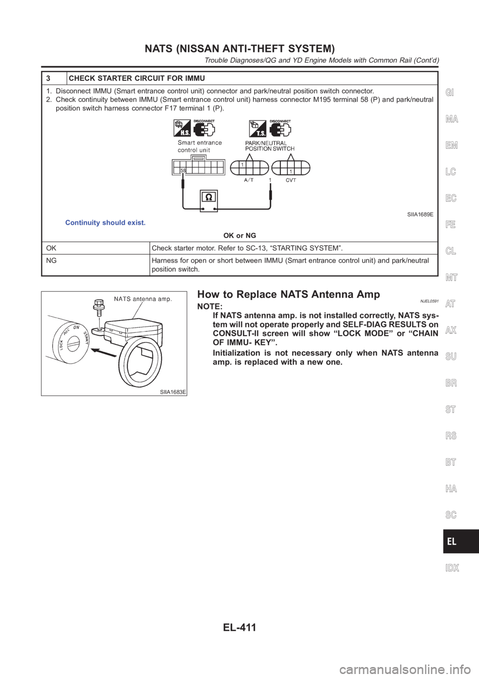
3 CHECK STARTER CIRCUIT FOR IMMU
1. Disconnect IMMU (Smart entrance control unit) connector and park/neutral position switch connector.
2. Check continuity between IMMU (Smart entrance control unit) harness connector M195 terminal 58 (P) and park/neutral
position switch harness connector F17 terminal 1 (P).
SIIA1689E
Continuity should exist.
OK or NG
OK Check starter motor. Refer to SC-13, “STARTING SYSTEM”.
NG Harness for open or short between IMMU (Smart entrance control unit) andpark/neutral
position switch.
SIIA1683E
How to Replace NATS Antenna AmpNJEL0591NOTE:
If NATS antenna amp. is not installed correctly, NATS sys-
tem will not operate properly and SELF-DIAG RESULTS on
CONSULT-II screen will show “LOCK MODE” or “CHAIN
OF IMMU- KEY”.
Initialization is not necessary only when NATS antenna
amp. is replaced with a new one.
GI
MA
EM
LC
EC
FE
CL
MT
AT
AX
SU
BR
ST
RS
BT
HA
SC
IDX
NATS (NISSAN ANTI-THEFT SYSTEM)
Trouble Diagnoses/QG and YD Engine Models with Common Rail (Cont’d)
EL-411
Page 2786 of 3189
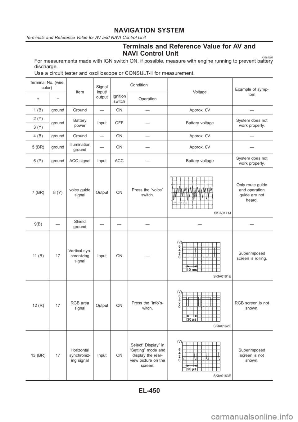
Terminals and Reference Value for AV and
NAVI Control Unit
NJEL0599For measurements made with IGN switch ON, if possible, measure with enginerunning to prevent battery
discharge.
Use a circuit tester and oscilloscope or CONSULT-ll for measurement.
Terminal No. (wire
color)
ItemSignal
input/
outputCondition
VoltageExample of symp-
tom
+−Ignition
switchOperation
1 (B) ground Ground — ON — Approx. 0V —
2 (Y)
groundBattery
powerInput OFF — Battery voltageSystem does not
work properly.
3 (Y)
4 (B) ground Ground — ON — Approx. 0V —
5 (BR) groundIllumination
ground— ON — Approx. 0V —
6 (P) ground ACC signal Input ACC — Battery voltageSystem does not
work properly.
7 (BR) 8 (Y)voice guide
signalOutput ONPress the “voice”
switch.
SKIA0171J
Only route guide
and operation
guide are not
heard.
9(B) —Shield
ground—— — — —
11 (B) 17Vertical syn-
chronizing
signalInput ON —
SKIA0161E
Superimposed
screen is rolling.
12 (R) 17RGB area
signalOutput ONPress the “info”s-
witch.
SKIA0162E
RGB screen is not
shown.
13 (BR) 17Horizontal
synchroniz-
ing signalInput ONSelect“ Display” in
“Setting” mode and
display the rear-
view picture on the
screen.
SKIA0163E
Superimposed
screen is not
shown.
NAVIGATION SYSTEM
Terminals and Reference Value for AV and NAVI Control Unit
EL-450
Page 2833 of 3189
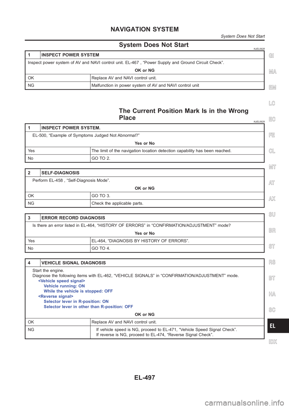
System Does Not StartNJEL0628
1 INSPECT POWER SYSTEM
Inspect power system of AV and NAVI control unit. EL-467 , “Power Supply andGround Circuit Check”.
OK or NG
OK Replace AV and NAVI control unit.
NG Malfunction in power system of AV and NAVI control unit
The Current Position Mark Is in the Wrong
Place
NJEL0629
1 INSPECT POWER SYSTEM.
EL-500, “Example of Symptoms Judged Not Abnormal?”
YesorNo
Yes The limit of the navigation location detection capability has been reached.
No GO TO 2.
2 SELF-DIAGNOSIS
Perform EL-458 , “Self-Diagnosis Mode”.
OK or NG
OK GO TO 3.
NG Check the applicable parts.
3 ERROR RECORD DIAGNOSIS
Is there an error listed in EL-464, “HISTORY OF ERRORS” in “CONFIRMATION/ADJUSTMENT” mode?
YesorNo
Yes EL-464, “DIAGNOSIS BY HISTORY OF ERRORS”.
No GO TO 4.
4 VEHICLE SIGNAL DIAGNOSIS
Start the engine.
Diagnose the following items with EL-462, “VEHICLE SIGNALS” in “CONFIRMATION/ADJUSTMENT” mode.
Vehicle running: ON
While the vehicle is stopped: OFF
Selector lever in R-position: ON
Selector lever in other than R-position: OFF
OK or NG
OK Replace AV and NAVI control unit.
NG If vehicle speed is NG, proceed to EL-471, “Vehicle Speed Signal Check”.
If reverse is NG, proceed to EL-474, “Reverse Signal Check”.
GI
MA
EM
LC
EC
FE
CL
MT
AT
AX
SU
BR
ST
RS
BT
HA
SC
IDX
NAVIGATION SYSTEM
System Does Not Start
EL-497
Page 2857 of 3189
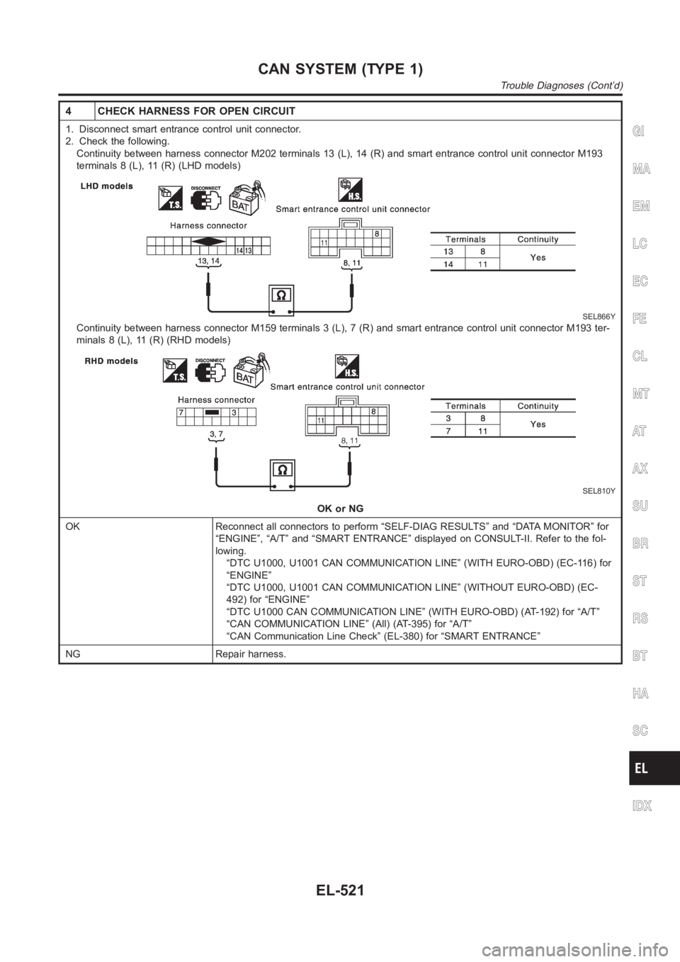
4 CHECK HARNESS FOR OPEN CIRCUIT
1. Disconnect smart entrance control unit connector.
2. Check the following.
Continuity between harness connector M202 terminals 13 (L), 14 (R) and smart entrance control unit connector M193
terminals 8 (L), 11 (R) (LHD models)
SEL866Y
Continuity between harness connector M159 terminals 3 (L), 7 (R) and smartentrance control unit connector M193 ter-
minals 8 (L), 11 (R) (RHD models)
SEL810Y
OK or NG
OK Reconnect all connectors to perform “SELF-DIAG RESULTS” and “DATA MONITOR” for
“ENGINE”, “A/T” and “SMART ENTRANCE” displayed on CONSULT-II. Refer to the fol-
lowing.
“DTC U1000, U1001 CAN COMMUNICATION LINE” (WITH EURO-OBD) (EC-116) for
“ENGINE”
“DTC U1000, U1001 CAN COMMUNICATION LINE” (WITHOUT EURO-OBD) (EC-
492) for “ENGINE”
“DTC U1000 CAN COMMUNICATION LINE” (WITH EURO-OBD) (AT-192) for “A/T”
“CAN COMMUNICATION LINE” (All) (AT-395) for “A/T”
“CAN Communication Line Check” (EL-380) for “SMART ENTRANCE”
NG Repair harness.
GI
MA
EM
LC
EC
FE
CL
MT
AT
AX
SU
BR
ST
RS
BT
HA
SC
IDX
CAN SYSTEM (TYPE 1)
Trouble Diagnoses (Cont’d)
EL-521
Page 2937 of 3189
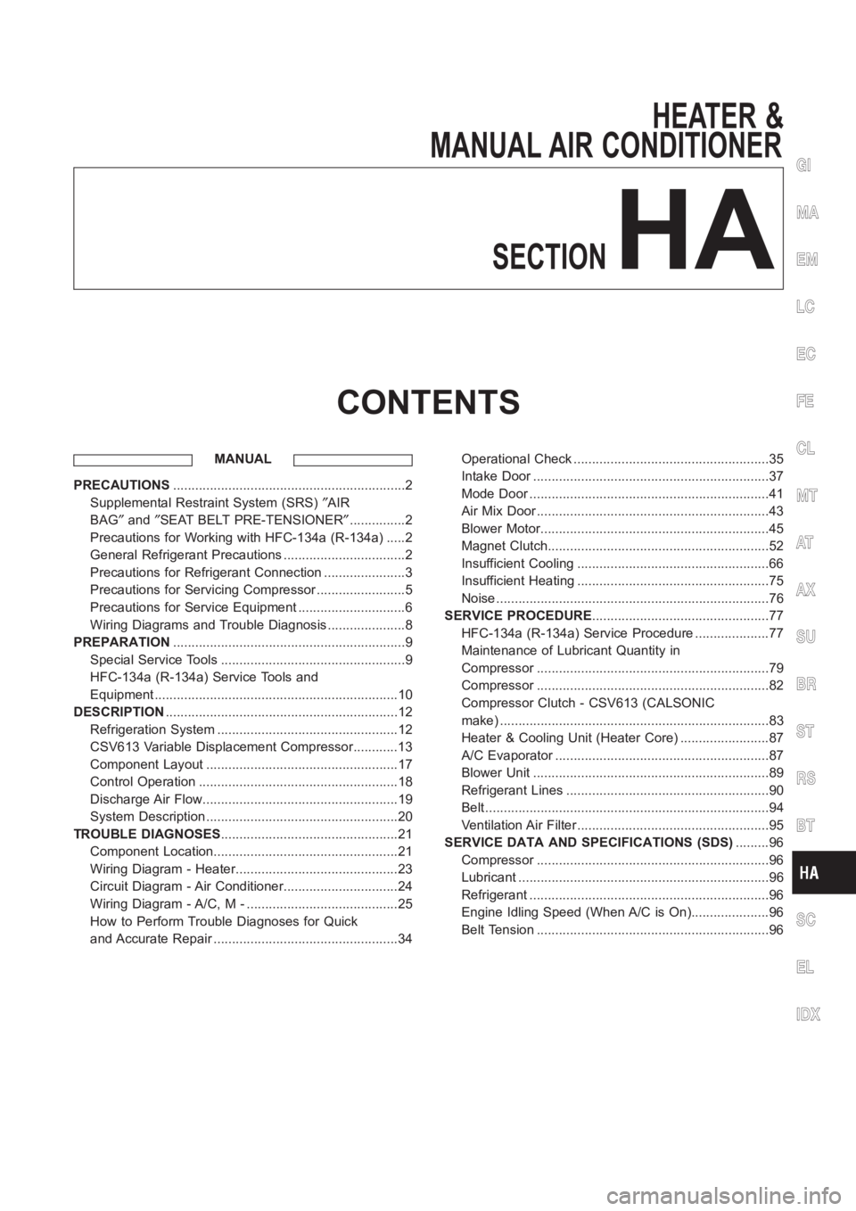
HEATER &
MANUAL AIR CONDITIONER
SECTION
HA
CONTENTS
MANUAL
PRECAUTIONS<0011001100110011001100110011001100110011001100110011001100110011001100110011001100110011001100110011001100110011001100110011001100110011001100110011001100110011001100110011001100110011001100110011001100
11001100110011001100110011001100110011001100110011[2
Supplemental Restraint System (SRS)″AIR
BAG″and″SEAT BELT PRE-TENSIONER″...............2
Precautions for Working with HFC-134a (R-134a) .....2
General Refrigerant Precautions .................................2
Precautions for Refrigerant Connection ......................3
Precautions for Servicing Compressor ........................5
Precautions for Service Equipment .............................6
Wiring Diagrams and Trouble Diagnosis .....................8
PREPARATION<0011001100110011001100110011001100110011001100110011001100110011001100110011001100110011001100110011001100110011001100110011001100110011001100110011001100110011001100110011001100110011001100110011001100
11001100110011001100110011001100110011001100110011[9
Special Service Tools ..................................................9
HFC-134a (R-134a) Service Tools and
Equipment <0011001100110011001100110011001100110011001100110011001100110011001100110011001100110011001100110011001100110011001100110011001100110011001100110011001100110011001100110011001100110011001100110011001100
11001100110011[............10
DESCRIPTION<0011001100110011001100110011001100110011001100110011001100110011001100110011001100110011001100110011001100110011001100110011001100110011001100110011001100110011001100110011001100110011001100110011001100
11001100110011001100110011001100110011001100110011[12
Refrigeration System .................................................12
CSV613 Variable Displacement Compressor............13
Component Layout ....................................................17
Control Operation ......................................................18
Discharge Air Flow.....................................................19
System Description ....................................................20
TROUBLE DIAGNOSES................................................21
Component Location..................................................21
Wiring Diagram - Heater............................................23
Circuit Diagram - Air Conditioner...............................24
Wiring Diagram - A/C, M - .........................................25
How to Perform Trouble Diagnoses for Quick
and Accurate Repair ..................................................34Operational Check .....................................................35
Intake Door <0011001100110011001100110011001100110011001100110011001100110011001100110011001100110011001100110011001100110011001100110011001100110011001100110011001100110011001100110011001100110011001100110011001100
1100110011[...........37
Mode Door <0011001100110011001100110011001100110011001100110011001100110011001100110011001100110011001100110011001100110011001100110011001100110011001100110011001100110011001100110011001100110011001100110011001100
110011001100110011[..........41
Air Mix Door <0011001100110011001100110011001100110011001100110011001100110011001100110011001100110011001100110011001100110011001100110011001100110011001100110011001100110011001100110011001100110011001100110011001100
1100110011[..........43
Blower Motor<0011001100110011001100110011001100110011001100110011001100110011001100110011001100110011001100110011001100110011001100110011001100110011001100110011001100110011001100110011001100110011001100110011001100
110011[..........45
Magnet Clutch<0011001100110011001100110011001100110011001100110011001100110011001100110011001100110011001100110011001100110011001100110011001100110011001100110011001100110011001100110011001100110011001100110011001100
11[.........52
Insufficient Cooling ....................................................66
Insufficient Heating ....................................................75
Noise <0011001100110011001100110011001100110011001100110011001100110011001100110011001100110011001100110011001100110011001100110011001100110011001100110011001100110011001100110011001100110011001100110011001100
110011001100110011001100110011[................76
SERVICE PROCEDURE................................................77
HFC-134a (R-134a) Service Procedure ....................77
Maintenance of Lubricant Quantity in
Compressor <0011001100110011001100110011001100110011001100110011001100110011001100110011001100110011001100110011001100110011001100110011001100110011001100110011001100110011001100110011001100110011001100110011001100
1100110011[..........79
Compressor <0011001100110011001100110011001100110011001100110011001100110011001100110011001100110011001100110011001100110011001100110011001100110011001100110011001100110011001100110011001100110011001100110011001100
1100110011[..........82
Compressor Clutch - CSV613 (CALSONIC
make) <0011001100110011001100110011001100110011001100110011001100110011001100110011001100110011001100110011001100110011001100110011001100110011001100110011001100110011001100110011001100110011001100110011001100
110011001100110011001100110011[...............83
Heater & Cooling Unit (Heater Core) ........................87
A/C Evaporator ..........................................................87
Blower Unit <0011001100110011001100110011001100110011001100110011001100110011001100110011001100110011001100110011001100110011001100110011001100110011001100110011001100110011001100110011001100110011001100110011001100
1100110011[...........89
Refrigerant Lines .......................................................90
Belt <0011001100110011001100110011001100110011001100110011001100110011001100110011001100110011001100110011001100110011001100110011001100110011001100110011001100110011001100110011001100110011001100110011001100
1100110011001100110011001100110011[..................94
Ventilation Air Filter ....................................................95
SERVICE DATA AND SPECIFICATIONS (SDS).........96
Compressor <0011001100110011001100110011001100110011001100110011001100110011001100110011001100110011001100110011001100110011001100110011001100110011001100110011001100110011001100110011001100110011001100110011001100
1100110011[..........96
Lubricant <0011001100110011001100110011001100110011001100110011001100110011001100110011001100110011001100110011001100110011001100110011001100110011001100110011001100110011001100110011001100110011001100110011001100
11001100110011[..............96
Refrigerant <0011001100110011001100110011001100110011001100110011001100110011001100110011001100110011001100110011001100110011001100110011001100110011001100110011001100110011001100110011001100110011001100110011001100
110011[.............96
Engine Idling Speed (When A/C is On).....................96
Belt Tension <0011001100110011001100110011001100110011001100110011001100110011001100110011001100110011001100110011001100110011001100110011001100110011001100110011001100110011001100110011001100110011001100110011001100
110011[...........96
GI
MA
EM
LC
EC
FE
CL
MT
AT
AX
SU
BR
ST
RS
BT
SC
EL
IDX
Page 2996 of 3189
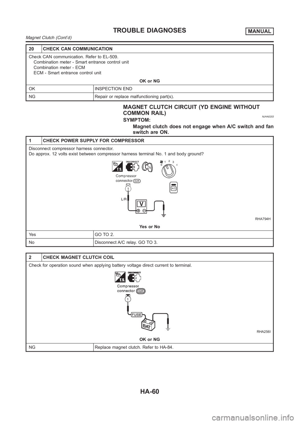
20 CHECK CAN COMMUNICATION
Check CAN communication. Refer to EL-509.
Combination meter - Smart entrance control unit
Combination meter - ECM
ECM - Smart entrance control unit
OK or NG
OK INSPECTION END
NG Repair or replace malfunctioning part(s).
MAGNET CLUTCH CIRCUIT (YD ENGINE WITHOUT
COMMON RAIL)
NJHA0203SYMPTOM:
Magnet clutch does not engage when A/C switch and fan
switch are ON.
1 CHECK POWER SUPPLY FOR COMPRESSOR
Disconnect compressor harness connector.
Do approx. 12 volts exist between compressor harness terminal No. 1 and body ground?
RHA794H
YesorNo
Ye s G O T O 2 .
No Disconnect A/C relay. GO TO 3.
2 CHECK MAGNET CLUTCH COIL
Check for operation sound when applying battery voltage direct current toterminal.
RHA256I
OK or NG
NG Replace magnet clutch. Refer to HA-84.
TROUBLE DIAGNOSESMANUAL
Magnet Clutch (Cont’d)
HA-60
Page 3119 of 3189
System DescriptionNJSC0004M/T MODELSNJSC0004S01Power is supplied at all times
through 40A fusible link (letterB, located in the fuse and fusible link box)
to ignition switch terminal 1.
With the ignition switch in START position, power is supplied
from ignition switch terminal 5
to smart entrance control unit terminal 58
from smart entrance control unit terminal 59
to starter motor harness connector terminal 1.
The starter motor plunger closes and provides a closed circuit between thebattery and starter motor. The
starter motor is grounded to the engine block. With power and ground supplied, cranking occurs and the engine
starts.
A/T MODELSNJSC0004S02Power is supplied at all times
through 40A fusible link (letterB, located in the fuse and fusible link box)
to ignition switch terminal 1.
With the ignition switch in the START position, power is supplied
from ignition switch terminal 5
to park/neutral position relay terminal 5.
With the ignition switch ON or START position, power is supplied
through 10A fuse [No. 20, located in the fuse block (J/B)]
to park/neutral position (PNP) relay terminal 1.
With the selector lever in the P or N position, ground is supplied
to park/neutral position relay terminal 2 through the park/neutral position switch
to smart entrance control unit terminal 59
from smart entrance control unit terminal 58
from body grounds, F9 and F10.
Then park/neutral position relay is energized and power is supplied
from park/neutral position relay terminal 3
to starter motor harness connector terminal 1.
The starter motor plunger closes and provides a closed circuit between thebattery and starter motor. The
starter motor is grounded to the engine block. With power and ground supplied, cranking occurs and the engine
starts.
GI
MA
EM
LC
EC
FE
CL
MT
AT
AX
SU
BR
ST
RS
BT
HA
EL
IDX
STARTING SYSTEM
System Description
SC-13
Page 3133 of 3189
System DescriptionNJSC0009The alternator provides DC voltage to operate the vehicle’s electrical system and to keep the battery charged.
The voltage output is controlled by the IC regulator.
Power is supplied at all times to alternator terminal 4 (S) through:
10A fuse (No. 39, located in the fuse and fusible link box).
Terminal B supplies power to charge the battery and operate the vehicle’s electrical system. Output voltage
is controlled by the IC regulator at terminal 4 (S) detecting the input voltage. The charging circuit is protected
by the 100A fusible link.
The alternator is grounded to the engine block.
With the ignition switch in the ON or START position, power is supplied
through 10A fuse [No. 30, located in the fuse block (J/B)]
to combination meter terminal 30
Ground is supplied to terminal 18 of the combination meter through terminal 3 (L) of the alternator. With power
and ground supplied, the charge warning lamp will illuminate. When the alternator is providing sufficient volt-
age with the engine running, the ground is opened and the charge warning lamp will go off.
If the charge warning lamp illuminates with the engine running, a fault is indicated.GI
MA
EM
LC
EC
FE
CL
MT
AT
AX
SU
BR
ST
RS
BT
HA
EL
IDX
CHARGING SYSTEM
System Description
SC-27