2003 NISSAN ALMERA N16 torque
[x] Cancel search: torquePage 1465 of 3189
PREPARATION
AT-9
D
E
F
G
H
I
J
K
L
MA
B
AT
PREPARATIONPFP:00100
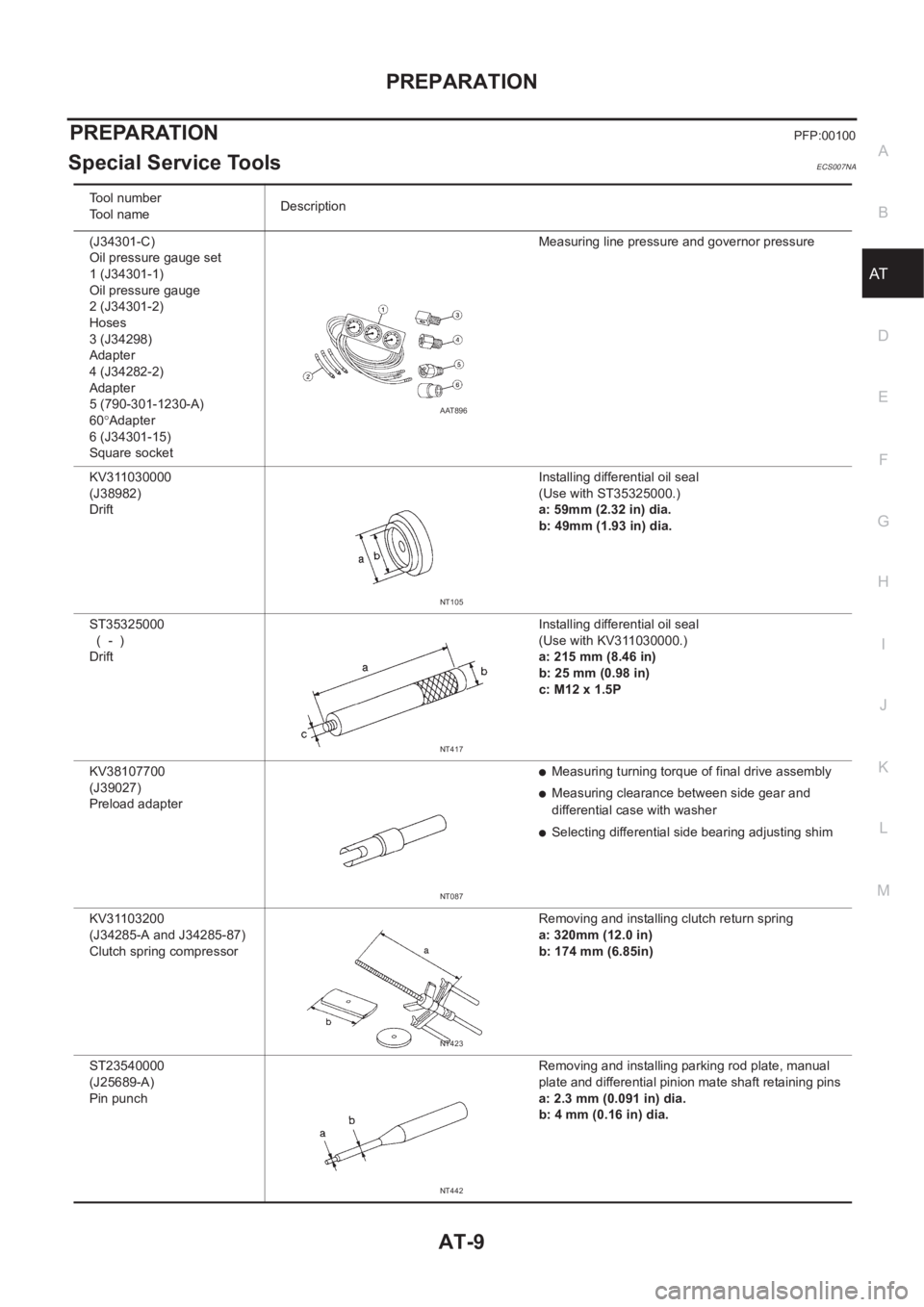
Special Service ToolsECS007NA
Tool number
Tool nameDescription
(J34301-C)
Oil pressure gauge set
1 (J34301-1)
Oil pressure gauge
2 (J34301-2)
Hoses
3 (J34298)
Adapter
4 (J34282-2)
Adapter
5 (790-301-1230-A)
60°Adapter
6 (J34301-15)
Square socketMeasuring line pressure and governor pressure
KV311030000
(J38982)
Drift Installing differential oil seal
(Use with ST35325000.)
a: 59mm (2.32 in) dia.
b: 49mm (1.93 in) dia.
ST35325000
( - )
Drift Installing differential oil seal
(Use with KV311030000.)
a: 215 mm (8.46 in)
b: 25 mm (0.98 in)
c: M12 x 1.5P
KV38107700
(J39027)
Preload adapter
●Measuring turning torque of final drive assembly
●Measuring clearance between side gear and
differential case with washer
●Selecting differential side bearing adjusting shim
KV31103200
(J34285-A and J34285-87)
Clutch spring compressor Removing and installing clutch return spring
a: 320mm (12.0 in)
b: 174 mm (6.85in)
ST23540000
(J25689-A)
Pin punch Removing and installing parking rod plate, manual
plate and differential pinion mate shaft retaining pins
a: 2.3 mm (0.091 in) dia.
b: 4 mm (0.16 in) dia.
AAT896
NT105
NT417
NT087
NT423
NT442
Page 1469 of 3189

A/T FLUID
AT-13
D
E
F
G
H
I
J
K
L
MA
B
AT
A/T FLUIDPFP:KLE40
Checking A/T FluidECS007NC
1. Warm up engine.
2. Check for fluid leakage.
3. Before driving, fluid level can be checked at fluid temperatures
of 30 to 50°C (86 to 122°F) using “COLD” range on dipstick.
a. Park vehicle on level surface and set parking brake.
b. Start engine and move selector lever through each gear posi-
tion. Leave selector lever in “P” position.
c. Check fluid level with engine idling.
d. Remove dipstick and note reading. If level is at low side of either
range, and fluid to the charging pipe.
e. Re-insert dipstick into charging pipe as far as it will go.
f. Remove dipstick and note reading. If reading is at low side of range, add fluid to the charging pipe.
Do not overfill.
4. Drive vehicle for approximately 5 minutes in urban areas.
5. Re-check fluid level at fluid temperatures of 50 to 80°C (122 to 176°F) using “HOT” range on dipstick.
6. Check fluid condition.
●If fluid is very dark or smells burned, refer to AT section for
checking operation of A/T. Flush cooling system after repair of
A/T.
●If A/T fluid contains frictional material (clutches, bands, etc.),
replace radiator and flush cooler line using cleaning solvent
and compressed air after repair of A/T. Refer to LC-16, "Radi-
ator".
Changing A/T FluidECS007ND
1. Warm up A/T fluid.
2. Stop engine.
3. Drain A/T fluid from drain plug and refill with new A/T fluid.
Always refill same volume with drained fluid.
4. Run engine at idle speed for five minutes.
5. Check fluid level and condition. Refer to AT- 1 3 , "
Checking A/T Fluid" . If fluid is still dirty, repeat steps 2
through 5.
SMA827CA
SMA853B
Fluid grade:
Genuine Nissan ATF or equivalent. Refer to MA-
19, "RECOMMENDED FLUID AND LUBRI-
CANTS".
Fluid capacity (With torque converter):
Approx. 7.7 (6-3/4 lmp qt)
Drain plug:
: 29 - 39 N·m (3.0 - 4.0 kg-m, 22 - 29 ft-lb)
SMA027D
Page 1474 of 3189

AT-18
OVERALL SYSTEM
Shift Mechanism
ECS007NI
CONSTRUCTION
FUNCTION OF CLUTCH AND BRAKE
CLUTCH AND BAND CHART
1. Torque converter 2. Oil pump 3. Input shaft
4. Brake band 5. Reverse clutch 6. High clutch
7. Front sun gear 8. Front pinion gear 9. Front internal gear
10. Front planetary carrier 11. Rear sun gear 12. Rear pinion gear
13. Rear internal gear 14. Rear planetary carrier 15. Forward clutch
16. Forward one-way clutch 17. Overrun clutch 18. Low one-way clutch
19. Low & reverse brake 20. Parking pawl 21. Parking gear
22. Output shaft 23. Idle gear 24. Output gear
SAT998I
Clutch and brake components Abbr. Function
5 Reverse clutch R/C To transmit input power to front sun gear 7 .
6 High clutch H/C To transmit input power to front planetary carrier 10 .
15 Forward clutch F/C To connect front planetary carrier 10 with forward one-way clutch 16 .
17 Overrun clutch O/C To connect front planetary carrier 10 with rear internal gear 13 .
4 Brake band B/B To lock front sun gear 7 .
16 Forward one-way clutch F/O.C When forward clutch 15 is engaged, to stop rear internal gear 13 from rotatin g in
opposite direction against engine revolution.
18 Low one-way clutch L/O.C To stop front planetary carrier 10 from rotating in opposite direction against
engine revolution.
19 Low & reverse brake L & R/B To lock front planetary carrier 10 .
Shift posi-
tionReverse
clutch
5High
clutch
6For-
ward
clutch
15Over-
run
clutch
17Band servo
Forward
one-way
clutch
16Low
one-
way
clutch
18Low &
revers
e brake
19Lock-
upRemarks
2nd
apply3rd
release4th
apply
PPA R K
POSITION
RREVERSE
POSITION
NNEUTRAL
POSITION
Page 1483 of 3189
OVERALL SYSTEM
AT-27
D
E
F
G
H
I
J
K
L
MA
B
AT
Control SystemECS007NJ
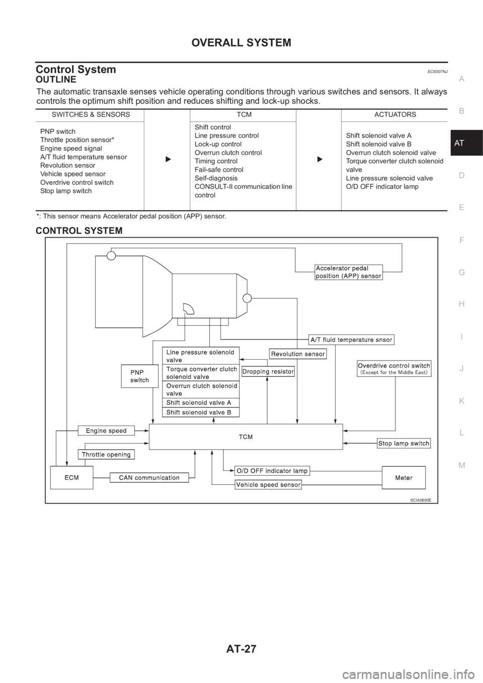
OUTLINE
The automatic transaxle senses vehicle operating conditions through various switches and sensors. It always
controls the optimum shift position and reduces shifting and lock-up shocks.
*: This sensor means Accelerator pedal position (APP) sensor.
CONTROL SYSTEM
SWITCHES & SENSORS TCM ACTUATORS
PNP switch
Throttle position sensor*
Engine speed signal
A/T fluid temperature sensor
Revolution sensor
Vehicle speed sensor
Overdrive control switch
Stop lamp switchShift control
Line pressure control
Lock-up control
Overrun clutch control
Timing control
Fail-safe control
Self-diagnosis
CONSULT-II communication line
controlShift solenoid valve A
Shift solenoid valve B
Overrun clutch solenoid valve
Torque converter clutch solenoid
valve
Line pressure solenoid valve
O/D OFF indicator lamp
SCIA0690E
Page 1484 of 3189
AT-28
OVERALL SYSTEM
TCM FUNCTION
The function of the TCM is to:
●Receive input signals sent from various switches and sensors.
●Determine required line pressure, shifting point, lock-up operation, and engine brake operation.
●Send required output signals to the respective solenoid valves.
INPUT/OUTPUT SIGNAL OF TCM
Control MechanismECS007NK
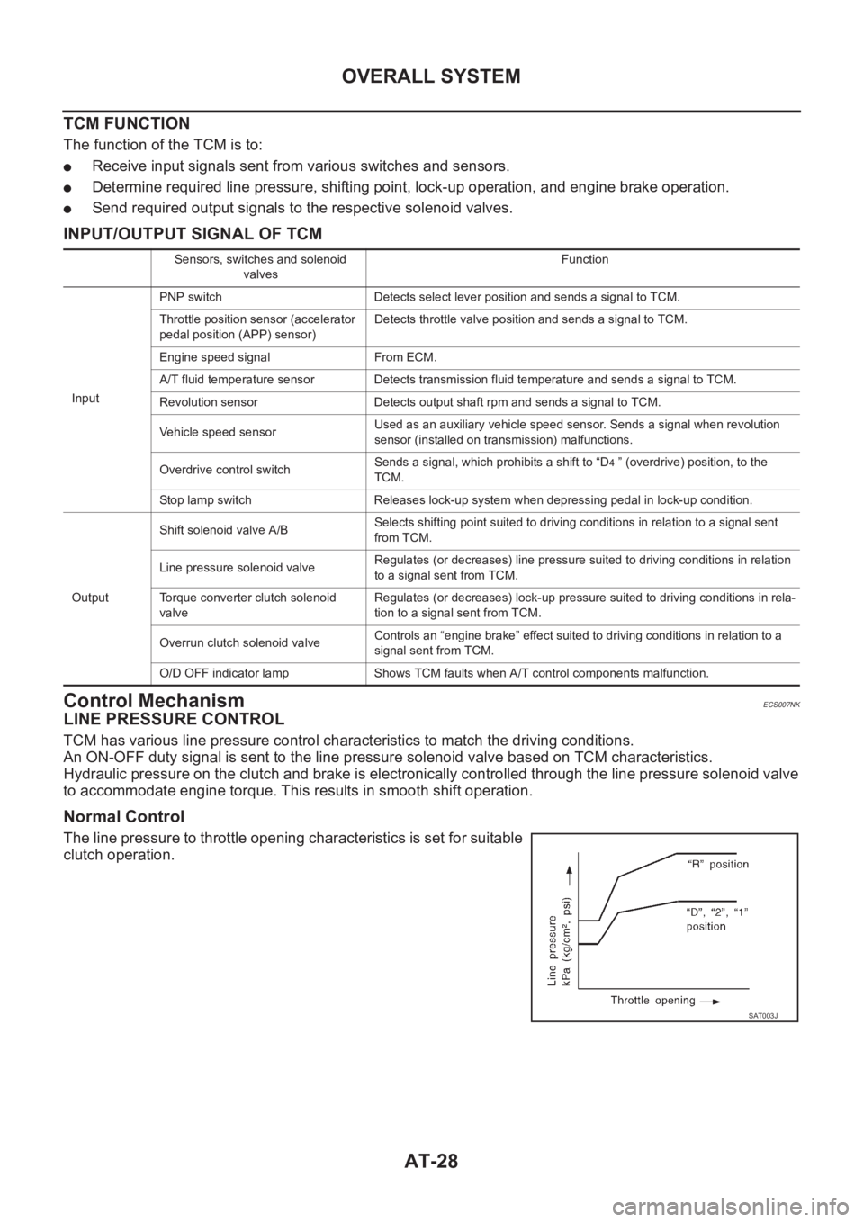
LINE PRESSURE CONTROL
TCM has various line pressure control characteristics to match the driving conditions.
An ON-OFF duty signal is sent to the line pressure solenoid valve based on TCM characteristics.
Hydraulic pressure on the clutch and brake is electronically controlled through the line pressure solenoid valve
to accommodate engine torque. This results in smooth shift operation.
Normal Control
The line pressure to throttle opening characteristics is set for suitable
clutch operation.
Sensors, switches and solenoid
valvesFunction
InputPNP switch Detects select lever position and sends a signal to TCM.
Throttle position sensor (accelerator
pedal position (APP) sensor)Detects throttle valve position and sends a signal to TCM.
Engine speed signal From ECM.
A/T fluid temperature sensor Detects transmission fluid temperature and sends a signal to TCM.
Revolution sensor Detects output shaft rpm and sends a signal to TCM.
Vehicle speed sensorUsed as an auxiliary vehicle speed sensor. Sends a signal when revolution
sensor (installed on transmission) malfunctions.
Overdrive control switchSends a signal, which prohibits a shift to “D
4 ” (overdrive) position, to the
TCM.
Stop lamp switch Releases lock-up system when depressing pedal in lock-up condition.
OutputShift solenoid valve A/BSelects shifting point suited to driving conditions in relation to a signal sent
from TCM.
Line pressure solenoid valveRegulates (or decreases) line pressure suited to driving conditions in relation
to a signal sent from TCM.
Torque converter clutch solenoid
valveRegulates (or decreases) lock-up pressure suited to driving conditions in rela-
tion to a signal sent from TCM.
Overrun clutch solenoid valveControls an “engine brake” effect suited to driving conditions in relation to a
signal sent from TCM.
O/D OFF indicator lamp Shows TCM faults when A/T control components malfunction.
SAT003J
Page 1485 of 3189
OVERALL SYSTEM
AT-29
D
E
F
G
H
I
J
K
L
MA
B
AT
Back-up Control (Engine Brake)
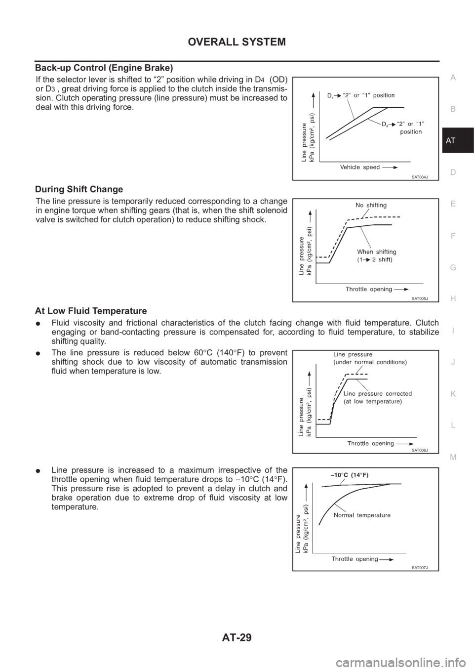
If the selector lever is shifted to “2” position while driving in D4 (OD)
or D
3 , great driving force is applied to the clutch inside the transmis-
sion. Clutch operating pressure (line pressure) must be increased to
deal with this driving force.
During Shift Change
The line pressure is temporarily reduced corresponding to a change
in engine torque when shifting gears (that is, when the shift solenoid
valve is switched for clutch operation) to reduce shifting shock.
At Low Fluid Temperature
●Fluid viscosity and frictional characteristics of the clutch facing change with fluid temperature. Clutch
engaging or band-contacting pressure is compensated for, according to fluid temperature, to stabilize
shifting quality.
●The line pressure is reduced below 60°C (140°F) to prevent
shifting shock due to low viscosity of automatic transmission
fluid when temperature is low.
●Line pressure is increased to a maximum irrespective of the
throttle opening when fluid temperature drops to −10°C (14°F).
This pressure rise is adopted to prevent a delay in clutch and
brake operation due to extreme drop of fluid viscosity at low
temperature.
SAT004J
SAT005J
SAT006J
SAT007J
Page 1486 of 3189
AT-30
OVERALL SYSTEM
SHIFT CONTROL
The shift is regulated entirely by electronic control to accommodate vehicle speed and varying engine opera-
tions. This is accomplished by electrical signals transmitted by the revolution sensor and throttle position sen-
sor. This results in improved acceleration performance and fuel economy.
Control of Shift Solenoid Valves A and B
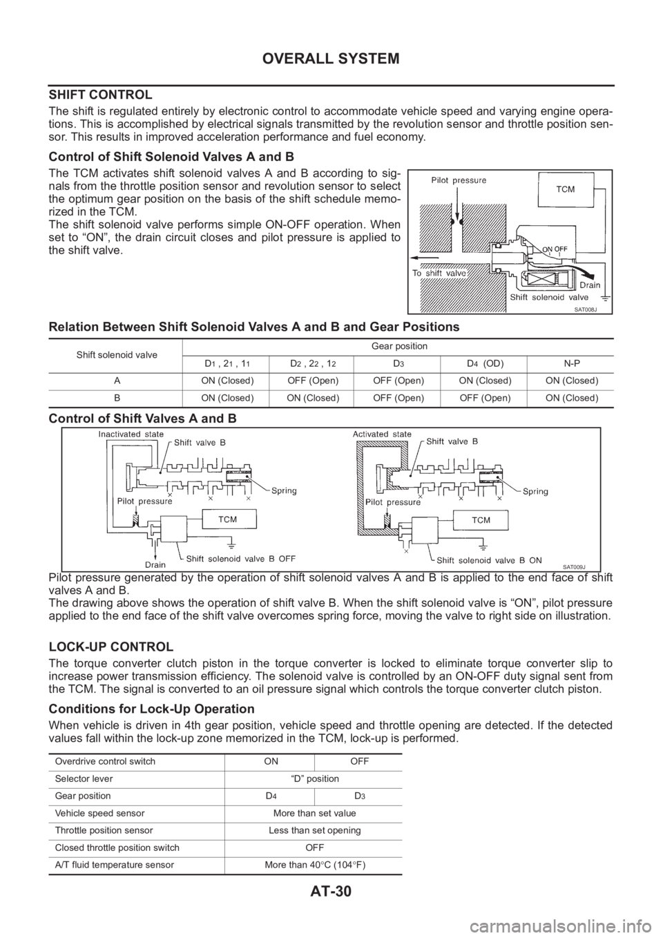
The TCM activates shift solenoid valves A and B according to sig-
nals from the throttle position sensor and revolution sensor to select
the optimum gear position on the basis of the shift schedule memo-
rized in the TCM.
The shift solenoid valve performs simple ON-OFF operation. When
set to “ON”, the drain circuit closes and pilot pressure is applied to
the shift valve.
Relation Between Shift Solenoid Valves A and B and Gear Positions
Control of Shift Valves A and B
Pilot pressure generated by the operation of shift solenoid valves A and B is applied to the end face of shift
valves A and B.
The drawing above shows the operation of shift valve B. When the shift solenoid valve is “ON”, pilot pressure
applied to the end face of the shift valve overcomes spring force, moving the valve to right side on illustration.
LOCK-UP CONTROL
The torque converter clutch piston in the torque converter is locked to eliminate torque converter slip to
increase power transmission efficiency. The solenoid valve is controlled by an ON-OFF duty signal sent from
the TCM. The signal is converted to an oil pressure signal which controls the torque converter clutch piston.
Conditions for Lock-Up Operation
When vehicle is driven in 4th gear position, vehicle speed and throttle opening are detected. If the detected
values fall within the lock-up zone memorized in the TCM, lock-up is performed.
SAT008J
Shift solenoid valveGear position
D1 , 21 , 11D2 , 22 , 12D3D4 (OD) N-P
A ON (Closed) OFF (Open) OFF (Open) ON (Closed) ON (Closed)
B ON (Closed) ON (Closed) OFF (Open) OFF (Open) ON (Closed)
SAT009J
Overdrive control switch ON OFF
Selector lever “D” position
Gear position D
4D3
Vehicle speed sensor More than set value
Throttle position sensor Less than set opening
Closed throttle position switch OFF
A/T fluid temperature sensor More than 40°C (104°F)
Page 1487 of 3189
OVERALL SYSTEM
AT-31
D
E
F
G
H
I
J
K
L
MA
B
AT
Torque Converter Clutch Solenoid Valve Control
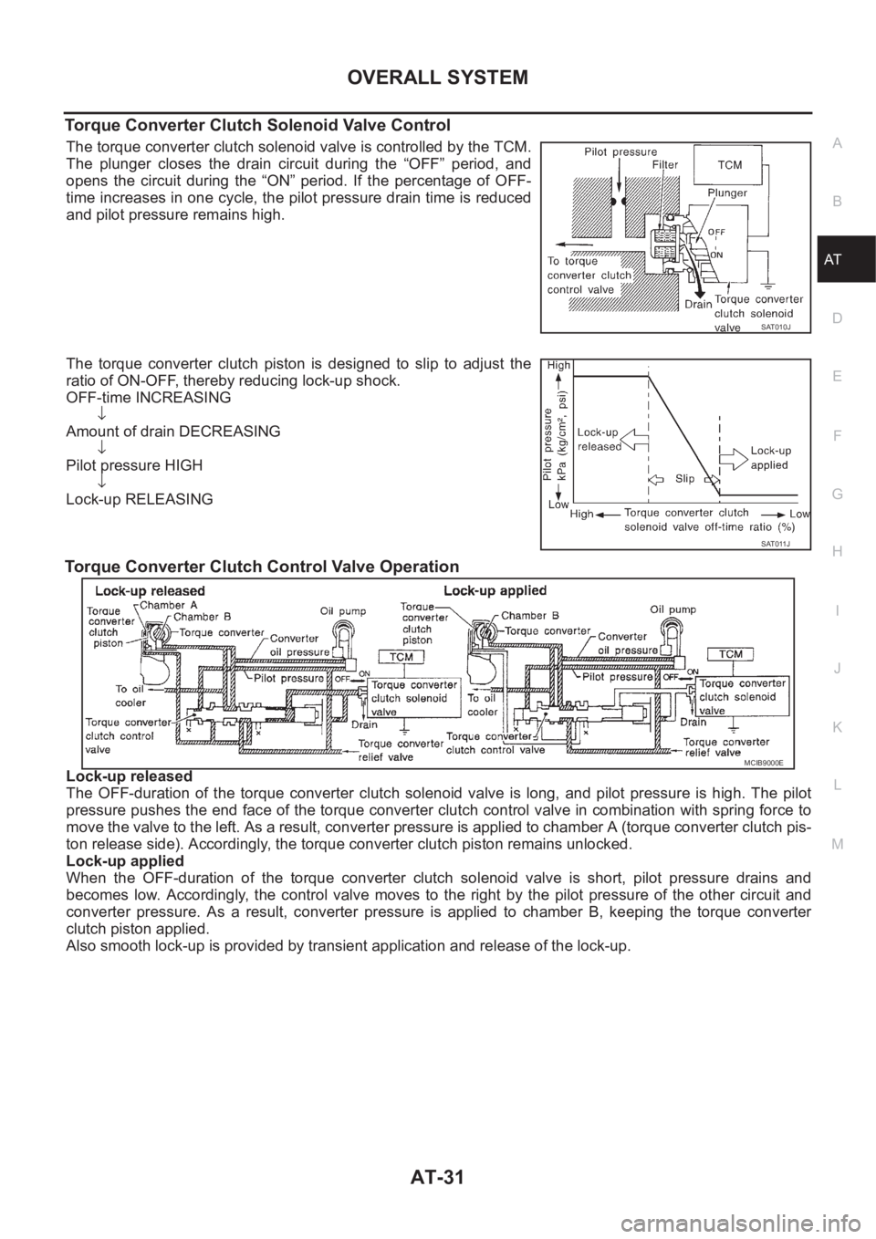
The torque converter clutch solenoid valve is controlled by the TCM.
The plunger closes the drain circuit during the “OFF” period, and
opens the circuit during the “ON” period. If the percentage of OFF-
time increases in one cycle, the pilot pressure drain time is reduced
and pilot pressure remains high.
The torque converter clutch piston is designed to slip to adjust the
ratio of ON-OFF, thereby reducing lock-up shock.
OFF-time INCREASING
↓
Amount of drain DECREASING
↓
Pilot pressure HIGH
↓
Lock-up RELEASING
Torque Converter Clutch Control Valve Operation
Lock-up released
The OFF-duration of the torque converter clutch solenoid valve is long, and pilot pressure is high. The pilot
pressure pushes the end face of the torque converter clutch control valve in combination with spring force to
move the valve to the left. As a result, converter pressure is applied to chamber A (torque converter clutch pis-
ton release side). Accordingly, the torque converter clutch piston remains unlocked.
Lock-up applied
When the OFF-duration of the torque converter clutch solenoid valve is short, pilot pressure drains and
becomes low. Accordingly, the control valve moves to the right by the pilot pressure of the other circuit and
converter pressure. As a result, converter pressure is applied to chamber B, keeping the torque converter
clutch piston applied.
Also smooth lock-up is provided by transient application and release of the lock-up.
SAT010J
SAT011J
MCIB9000E