Page 1404 of 3189
SMT731D
11. Install selector, selector shaft, and selector shaft pin into clutch
housing.
SMT732D
12. Hammer the welch plug (selector shaft side) with a general-
purpose drift [OD: 12 mm (0.47 in)].
CAUTION:
Do not reuse welch plug.
SMT733DA
SMT734D
13. Install select check leaf spring, return spring, steel ball, reverse
gate, selector arm, bushing, and return bearing. Then, tighten
two reamer bolts with specified torque.
CAUTION:
Use correct reamer bolts for each installation point, because
each bolt has a different length.
SMT735D
14. Install oil pocket.
ASSEMBLYRS5F70A
Clutch Housing (Cont’d)
MT-84
Page 1405 of 3189
SMT736D
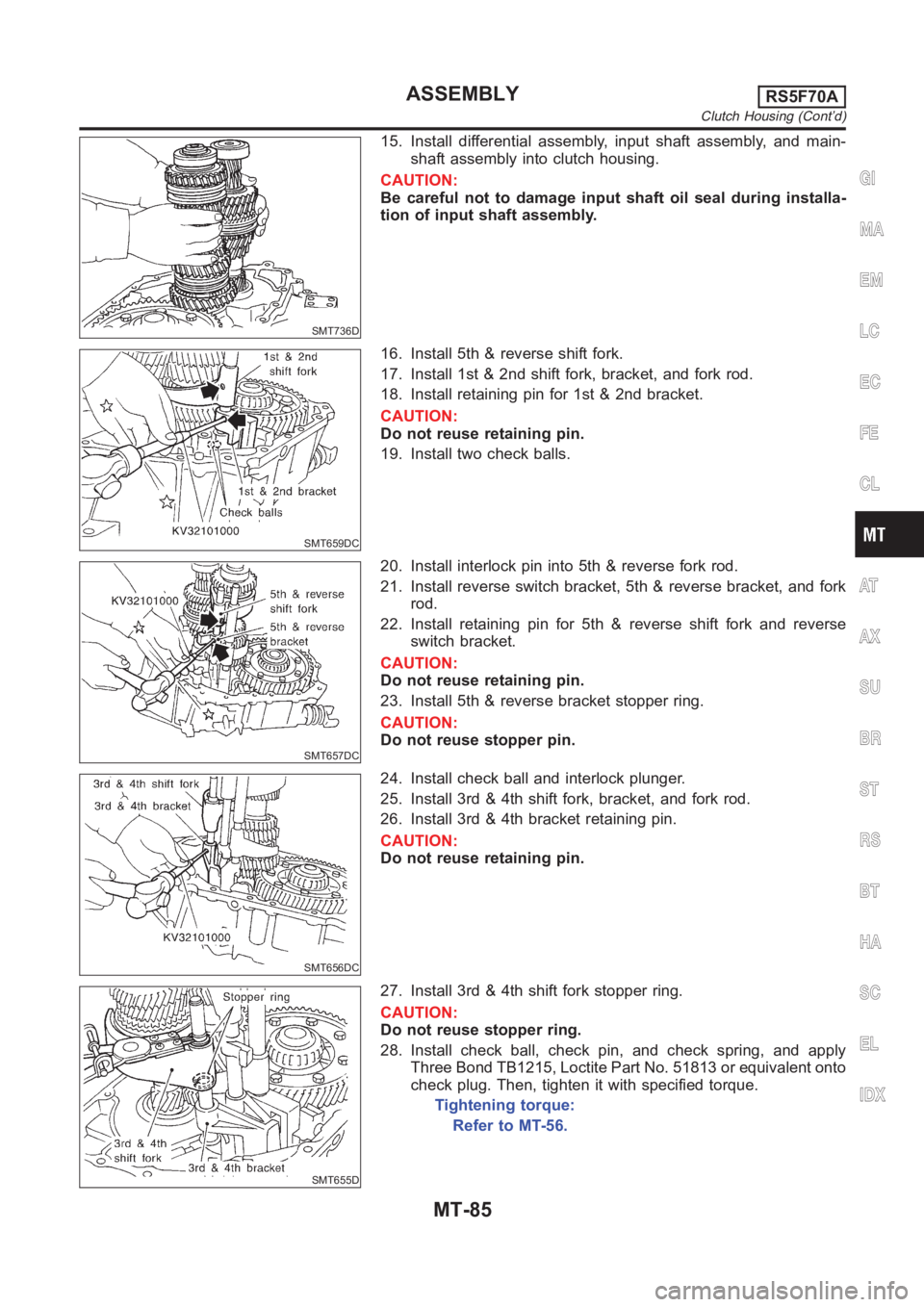
15. Install differential assembly, input shaft assembly, and main-
shaft assembly into clutch housing.
CAUTION:
Be careful not to damage input shaft oil seal during installa-
tion of input shaft assembly.
SMT659DC
16. Install 5th & reverse shift fork.
17. Install 1st & 2nd shift fork, bracket, and fork rod.
18. Install retaining pin for 1st & 2nd bracket.
CAUTION:
Do not reuse retaining pin.
19. Install two check balls.
SMT657DC
20. Install interlock pin into 5th & reverse fork rod.
21. Install reverse switch bracket, 5th & reverse bracket, and fork
rod.
22. Install retaining pin for 5th & reverse shift fork and reverse
switch bracket.
CAUTION:
Do not reuse retaining pin.
23. Install 5th & reverse bracket stopper ring.
CAUTION:
Do not reuse stopper pin.
SMT656DC
24. Install check ball and interlock plunger.
25. Install 3rd & 4th shift fork, bracket, and fork rod.
26. Install 3rd & 4th bracket retaining pin.
CAUTION:
Do not reuse retaining pin.
SMT655D
27. Install 3rd & 4th shift fork stopper ring.
CAUTION:
Do not reuse stopper ring.
28. Install check ball, check pin, and check spring, and apply
Three Bond TB1215, Loctite Part No. 51813 or equivalent onto
check plug. Then, tighten it with specified torque.
Tightening torque:
Refer to MT-56.
GI
MA
EM
LC
EC
FE
CL
AT
AX
SU
BR
ST
RS
BT
HA
SC
EL
IDX
ASSEMBLYRS5F70A
Clutch Housing (Cont’d)
MT-85
Page 1407 of 3189
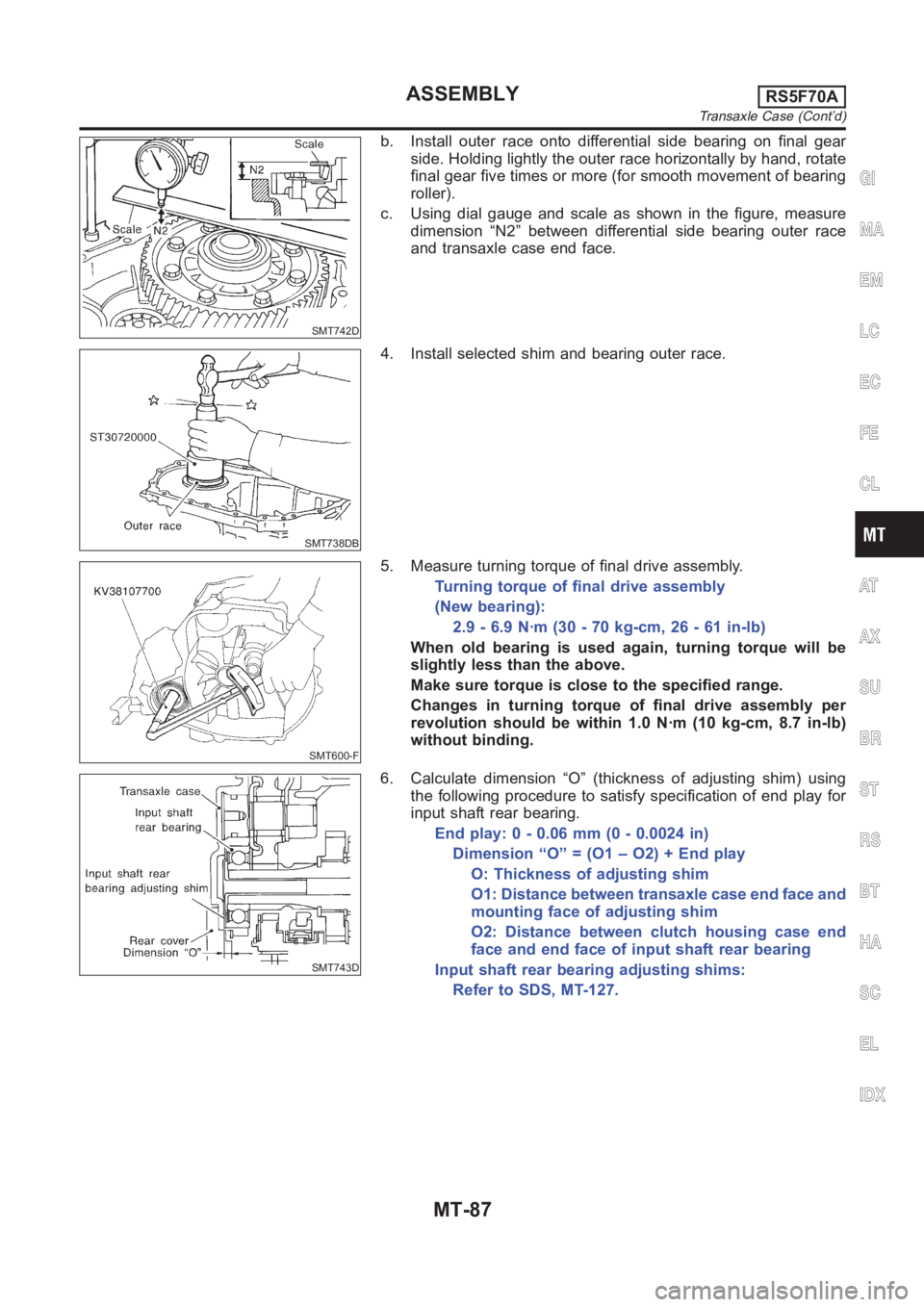
SMT742D
b. Install outer race onto differential side bearing on final gear
side. Holding lightly the outer race horizontally by hand, rotate
final gear five times or more (for smooth movement of bearing
roller).
c. Using dial gauge and scale as shown in the figure, measure
dimension “N2” between differential side bearing outer race
and transaxle case end face.
SMT738DB
4. Install selected shim and bearing outer race.
SMT600-F
5. Measure turning torque of final drive assembly.
Turning torque of final drive assembly
(New bearing):
2.9 - 6.9 N·m (30 - 70 kg-cm, 26 - 61 in-lb)
When old bearing is used again, turning torque will be
slightly less than the above.
Make sure torque is close to the specified range.
Changes in turning torque of final drive assembly per
revolution should be within 1.0 N·m (10 kg-cm, 8.7 in-lb)
without binding.
SMT743D
6. Calculate dimension “O” (thickness of adjusting shim) using
the following procedure to satisfy specification of end play for
input shaft rear bearing.
End play: 0 - 0.06 mm (0 - 0.0024 in)
Dimension “O” = (O1 – O2) + End play
O: Thickness of adjusting shim
O1: Distance between transaxle case end face and
mounting face of adjusting shim
O2: Distance between clutch housing case end
face and end face of input shaft rear bearing
Input shaft rear bearing adjusting shims:
Refer to SDS, MT-127.
GI
MA
EM
LC
EC
FE
CL
AT
AX
SU
BR
ST
RS
BT
HA
SC
EL
IDX
ASSEMBLYRS5F70A
Transaxle Case (Cont’d)
MT-87
Page 1409 of 3189
SMT649D
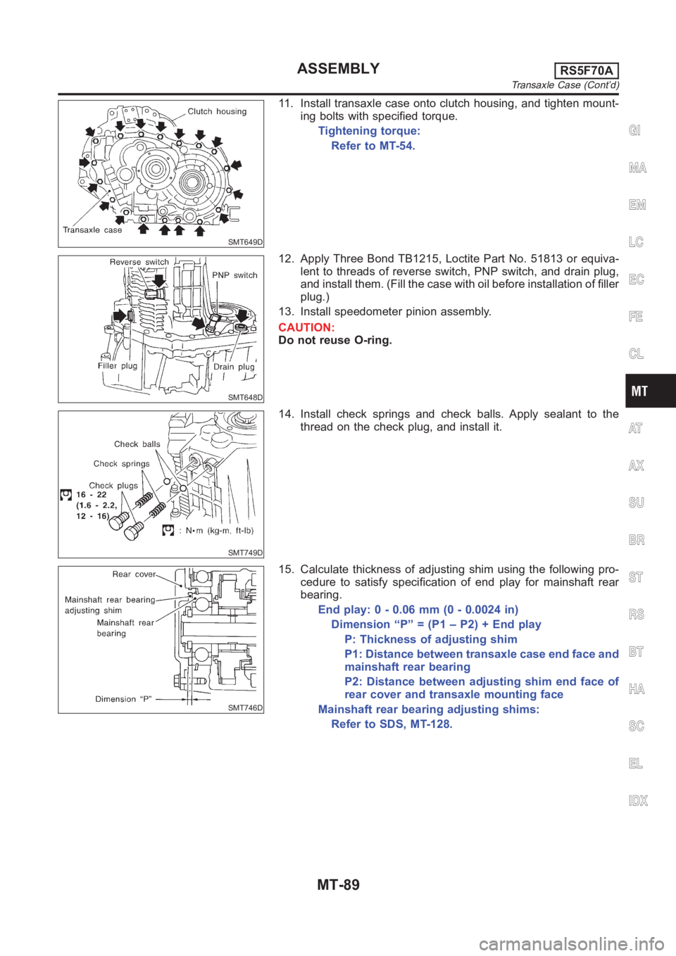
11. Install transaxle case onto clutch housing, and tighten mount-
ing bolts with specified torque.
Tightening torque:
Refer to MT-54.
SMT648D
12. Apply Three Bond TB1215, Loctite Part No. 51813 or equiva-
lent to threads of reverse switch, PNP switch, and drain plug,
and install them. (Fill the case with oil before installation of filler
plug.)
13. Install speedometer pinion assembly.
CAUTION:
Do not reuse O-ring.
SMT749D
14. Install check springs and check balls. Apply sealant to the
thread on the check plug, and install it.
SMT746D
15. Calculate thickness of adjusting shim using the following pro-
cedure to satisfy specification of end play for mainshaft rear
bearing.
End play: 0 - 0.06 mm (0 - 0.0024 in)
Dimension “P” = (P1 – P2) + End play
P: Thickness of adjusting shim
P1: Distance between transaxle case end face and
mainshaft rear bearing
P2: Distance between adjusting shim end face of
rear cover and transaxle mounting face
Mainshaft rear bearing adjusting shims:
Refer to SDS, MT-128.
GI
MA
EM
LC
EC
FE
CL
AT
AX
SU
BR
ST
RS
BT
HA
SC
EL
IDX
ASSEMBLYRS5F70A
Transaxle Case (Cont’d)
MT-89
Page 1411 of 3189
SMT644D
21. Install selected snap ring.
CAUTION:
Do not reuse snap ring.
22. Apply gear oil to rear cover O-ring, and install rear cover, side
cover gasket, and side cover. Then tighten mounting bolts with
specified torque.
Tightening torque:
Refer to MT-54.
CAUTION:
Do not reuse mounting bolts for rear cover and side cover.
GI
MA
EM
LC
EC
FE
CL
AT
AX
SU
BR
ST
RS
BT
HA
SC
EL
IDX
ASSEMBLYRS5F70A
Transaxle Case (Cont’d)
MT-91
Page 1431 of 3189
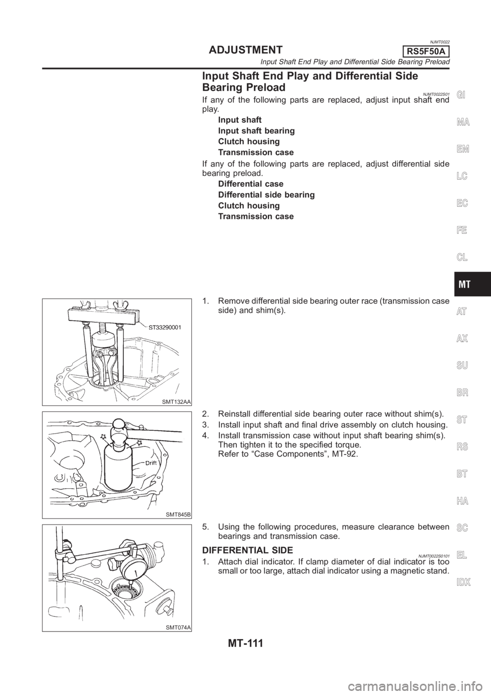
NJMT0022
Input Shaft End Play and Differential Side
Bearing Preload
NJMT0022S01If any of the following parts are replaced, adjust input shaft end
play.
Input shaft
Input shaft bearing
Clutch housing
Transmission case
If any of the following parts are replaced, adjust differential side
bearing preload.
Differential case
Differential side bearing
Clutch housing
Transmission case
SMT132AA
1. Remove differential side bearing outer race (transmission case
side) and shim(s).
SMT845B
2. Reinstall differential side bearing outer race without shim(s).
3. Install input shaft and final drive assembly on clutch housing.
4. Install transmission case without input shaft bearing shim(s).
Then tighten it to the specified torque.
Refer to “Case Components”, MT-92.
SMT074A
5. Using the following procedures, measure clearance between
bearings and transmission case.
DIFFERENTIAL SIDENJMT0022S01011. Attach dial indicator. If clamp diameter of dial indicator is too
small or too large, attach dial indicator using a magnetic stand.
GI
MA
EM
LC
EC
FE
CL
AT
AX
SU
BR
ST
RS
BT
HA
SC
EL
IDX
ADJUSTMENTRS5F50A
Input Shaft End Play and Differential Side Bearing Preload
MT-111
Page 1432 of 3189
SMT075AA
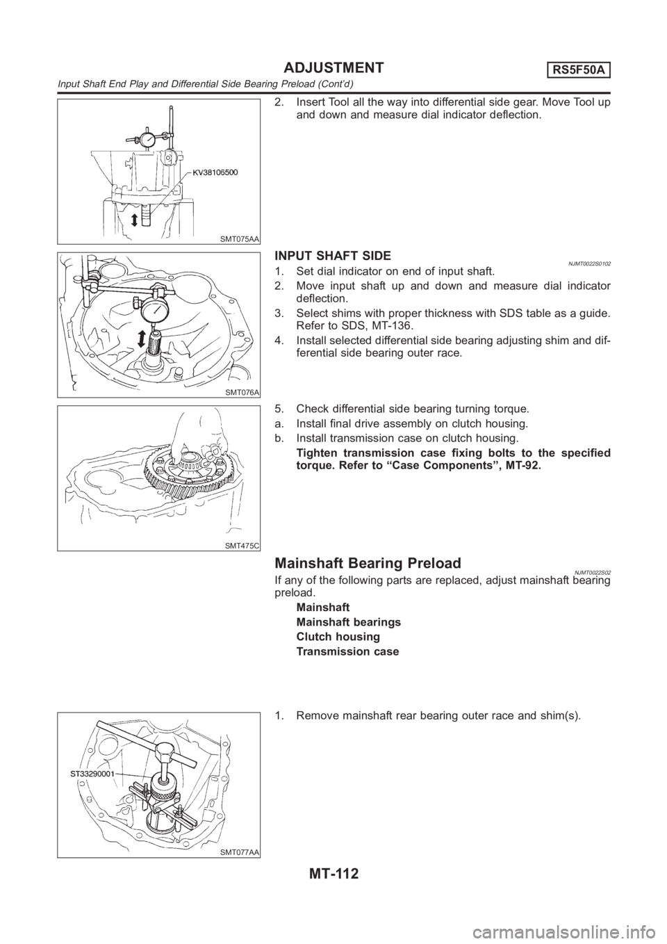
2. Insert Tool all the way into differential side gear. Move Tool up
and down and measure dial indicator deflection.
SMT076A
INPUTSHAFTSIDENJMT0022S01021. Set dial indicator on end of input shaft.
2. Move input shaft up and down and measure dial indicator
deflection.
3. Select shims with proper thickness with SDS table as a guide.
Refer to SDS, MT-136.
4. Install selected differential side bearing adjusting shim and dif-
ferential side bearing outer race.
SMT475C
5. Check differential side bearing turning torque.
a. Install final drive assembly on clutch housing.
b. Install transmission case on clutch housing.
Tighten transmission case fixing bolts to the specified
torque. Refer to “Case Components”, MT-92.
Mainshaft Bearing PreloadNJMT0022S02If any of the following parts are replaced, adjust mainshaft bearing
preload.
Mainshaft
Mainshaft bearings
Clutch housing
Transmission case
SMT077AA
1. Remove mainshaft rear bearing outer race and shim(s).
ADJUSTMENTRS5F50A
Input Shaft End Play and Differential Side Bearing Preload (Cont’d)
MT-112
Page 1433 of 3189
SMT644AA
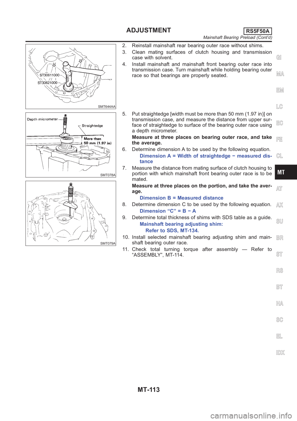
2. Reinstall mainshaft rear bearing outer race without shims.
3. Clean mating surfaces of clutch housing and transmission
case with solvent.
4. Install mainshaft and mainshaft front bearing outer race into
transmission case. Turn mainshaft while holding bearing outer
race so that bearings are properly seated.
SMT078A
SMT079A
5. Put straightedge [width must be more than 50 mm (1.97 in)] on
transmission case, and measure the distance from upper sur-
face of straightedge to surface of the bearing outer race using
a depth micrometer.
Measure at three places on bearing outer race, and take
the average.
6. Determine dimension A to be used by the following equation.
Dimension A = Width of straightedge − measured dis-
tance
7. Measure the distance from mating surface of clutch housing to
portion with which mainshaft front bearing outer race is to be
mated.
Measure at three places on the portion, and take the aver-
age.
Dimension B = Measured distance
8. Determine dimension C to be used by the following equation.
Dimension “C” = B − A
9. Determine total thickness of shims with SDS table as a guide.
Mainshaft bearing adjusting shim:
Refer to SDS, MT-134.
10. Install selected mainshaft bearing adjusting shim and main-
shaft bearing outer race.
11. Check total turning torque after assembly — Refer to
“ASSEMBLY”, MT-114.
GI
MA
EM
LC
EC
FE
CL
AT
AX
SU
BR
ST
RS
BT
HA
SC
EL
IDX
ADJUSTMENTRS5F50A
Mainshaft Bearing Preload (Cont’d)
MT-113