Page 103 of 392

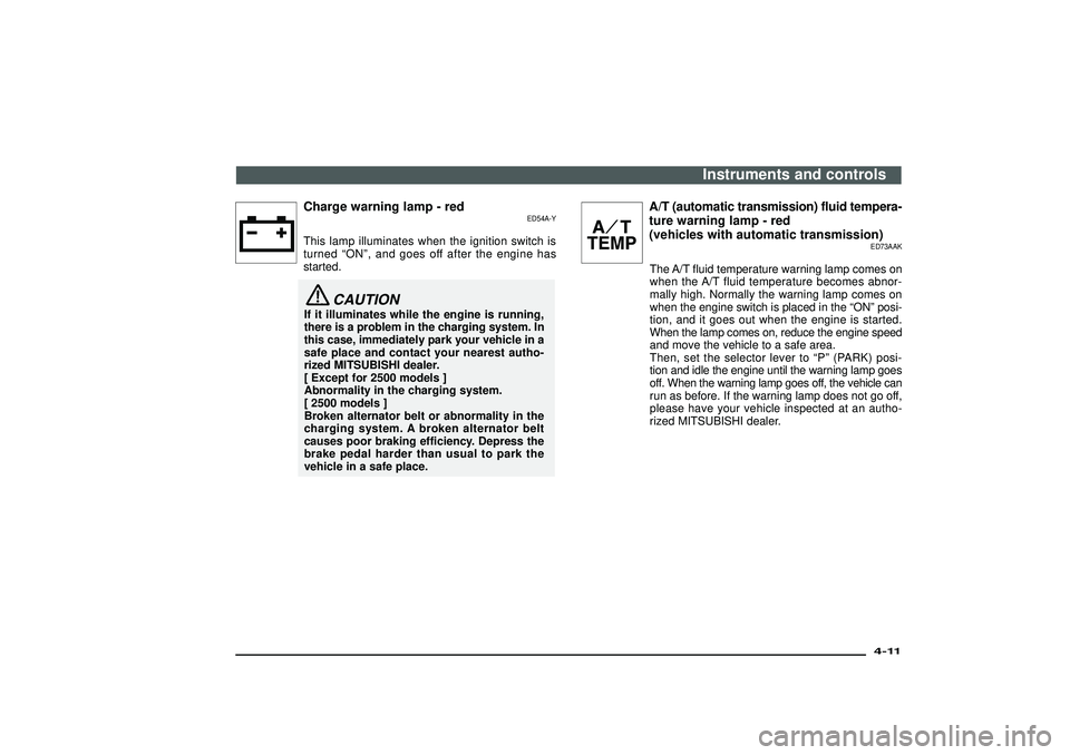
Charge warning lamp - red
ED54A-Y
This lamp illuminates when the ignition switch is
turned“ON ”, and goes off after the engine has
started.
CAUTION
If it illuminates while the engine is running,
there is a problem in the charging system. In
this case, immediately park your vehicle in a
safe place and contact your nearest autho-
rized MITSUBISHI dealer.
[ Except for 2500 models ]
Abnormality in the charging system.
[ 2500 models ]
Broken alternator belt or abnormality in the
charging system. A broken alternator belt
causes poor braking efficiency. Depress the
brake pedal harder than usual to park the
vehicle in a safe place.
A/T (automatic transmission) fluid tempera-
ture warning lamp - red
(vehicles with automatic transmission)
ED73AAK
The A/T fluid temperature warning lamp comes on
when the A/T fluid temperature becomes abnor-
mally high. Normally the warning lamp comes on
when the engine switch is placed in the “ON ”posi-
tion, and it goes out when the engine is started.
When the lamp comes on, reduce the engine speed
and move the vehicle to a safe area.
Then, set the selector lever to “P”(PARK) posi-
tion and idle the engine until the warning lamp goes
off. When the warning lamp goes off, the vehicle can
run as before. If the warning lamp does not go off,
please have your vehicle inspected at an autho-
rized MITSUBISHI dealer.
Instruments and controls
4-11
Div:
Out put date:
Page 330 of 392

N29B218E
Engine compartmentNO Symbol Electric systemCapacity
1
Alternator 120A
2Fuse (+B) 60A
3Ignition switch 40A
NO Symbol Electric systemCapacity
4
Electrical window control 30A
5Engine control 20A
6Fuel pump 20A
7Rear air conditioning 25A
8Accessory socket 15A
9Fuel line heater 25ADaytime running lamp 15A
10Condenser fan motor 25A
11Rear air conditioning 20A
12Horn 10AWiper deicer 15A
13Horn 10A
14Automatic transmission 20A
15Hazard warning flasher 10A
16Stop lamps 15A
NO Symbol Electric systemCapacity
17
Radio 10A
18Room lamp 10A
19Air conditioning 10A
20Front fog lamps 20A
21Horn 10A
22Windscreen wiper 20A
23Tail lamps (right) 10A
24Tail lamps (left) 10A
25Headlamp low beam
(right)10A
26Headlamp low beam (left) 10A
27Headlamp upper beam
(right)10A
28Headlamp upper beam
(left)10A
29 - - -
30Heater 50A
•Some fuses may not be installed on your vehicle,
depending on the vehicle model or specifications.
•The table above shows the main equipment corre-
sponding to each fuse.
For emergencies
8-32Div:
Out put date:
Page 374 of 392
Electrical system
EP01GOE
Item 2500 models 3200 models 3500 models
Voltage12V
Battery type 95D31L (622CCA/159RC)75D23L (520CCA/118RC),
80D26L* (620CCA/135RC)
Alternator capacity 105 A 125 A, 140 A* 125 A
Spark plug type NGK−IZFR5B (Iridium tipped)
*: Optional equipment
Tyres and wheels
EP01HOE
Item2500, 3200 models
3500 models
GL, GLX GLS
Tyre Size 235/80R16 109S, 265/70R16 112S* 265/70R16 112S 265/70R16 112H
WheelSize 16×6JJ (St), 16×7JJ (Al)* 16×7JJ (Al) 16×7JJ (Al)
Offset 46 mm
*: Optional equipment
Specifications
10-10Div:
Out put date: