Page 840 of 4500
c. Remove the O-ring from the transmission revolution sensor.
Fig. 21: Removing Bolt And Transmission Revolution Sensor
Courtesy of TOYOTA MOTOR SALES, U.S.A., INC.
2.REMOVE TRANSMISSION REVOLUTION SENSOR (SP2 SENSOR)
a. Disconnect the transmission revolution sensor connector.
b. Remove the bolt and transmission revolution sensor.
c. Remove the O-rin
g from the transmission revolution sensor.
Page 841 of 4500
Fig. 22: Removing Bolt And Transmission Revolution Sensor
Courtesy of TOYOTA MOTOR SALES, U.S.A., INC.
3.INSTALL TRANSMISSION REVOLUTION SENSOR (SP2 SENSOR)
a. Coat a new O-ring with ATF and install it to the transmission revolution sensor.
b. Install the transmission revolution sensor with the bolt.
Torque: 5.4 N.m (55 kgf.cm, 48 in..lbf)
c. Connect the transmission revolution sensor connector.
Page 1745 of 4500
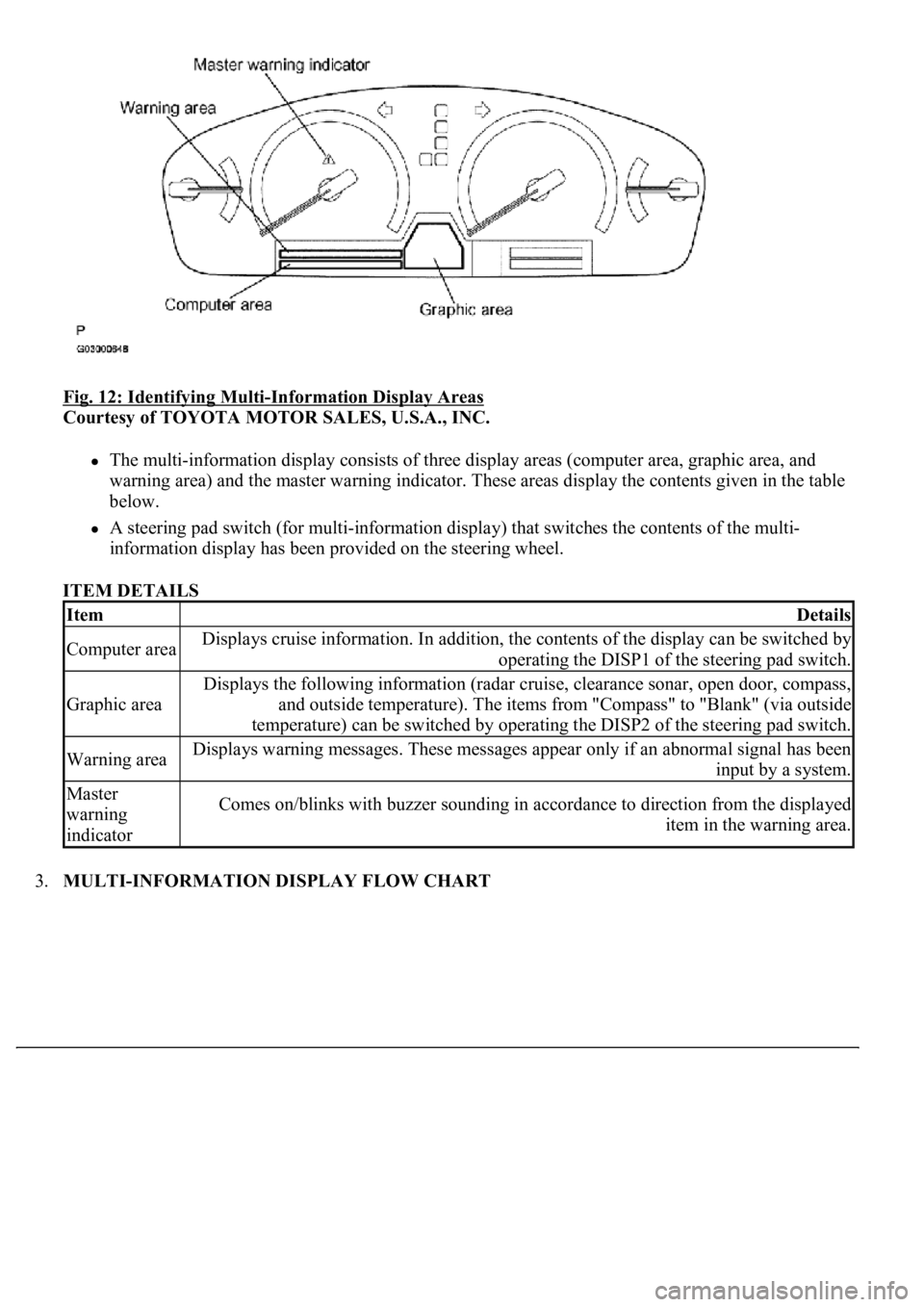
Fig. 12: Identifying Multi-Information Display Areas
Courtesy of TOYOTA MOTOR SALES, U.S.A., INC.
The multi-information display consists of three display areas (computer area, graphic area, and
warning area) and the master warning indicator. These areas display the contents given in the table
below.
A steering pad switch (for multi-information display) that switches the contents of the multi-
<004c0051004900520055005000440057004c0052005100030047004c00560053004f0044005c0003004b004400560003004500480048005100030053005500520059004c00470048004700030052005100030057004b004800030056005700480048005500
4c0051004a0003005a004b00480048004f001100030003[
ITEM DETAILS
3.MULTI-INFORMATION DISPLAY FLOW CHART
ItemDetails
Computer areaDisplays cruise information. In addition, the contents of the display can be switched by
operating the DISP1 of the steering pad switch.
Graphic area
Displays the following information (radar cruise, clearance sonar, open door, compass,
and outside temperature). The items from "Compass" to "Blank" (via outside
temperature) can be switched by operating the DISP2 of the steering pad switch.
Warning areaDisplays warning messages. These messages appear only if an abnormal signal has been
input by a system.
Master
warning
indicatorComes on/blinks with buzzer sounding in accordance to direction from the displayed
item in the warning area.
Page 1750 of 4500
INSPECTION ).
b. Computer area
The items from "Range Over ***/Range Approx ***" to "BLANK" can be changed with the
DISP1 (switch) of the steering pad switch.
c. Graphic area
Open Door Display:
<0037004b004800030047004c00560053004f0044005c0003004c005600030056004b0052005a00510003005a004b00480051000300440051005c00030052004900030057004b00480003004700520052005500560003004400550048000300520053004800
51005600110003[
HINT:
If the warning item other than the door warning is detected at the same time, the master warning
comes on/blinks in accordance to direction from the displayed item in the warning area.
Park Sonar Display:
See HOW TO PROCEED WITH TROUBLESHOOTING for details on the park sonar display.
The display blinks when the clearance is the closest.
Others:
The items "COMPASS", "OUTSIDE TEMPERATURE" and "BLANK" can be changed with the
DISP2 (switch) of the steering pad switch.
While +B is connected, the mode that was on when the ignition switch was turned off the last time
is displayed.
When the display is changed from radar cruise, it is displayed for only 6 seconds and then returns
to the radar cruise display.
While the radar cruise is on, "RADAR CRUISE READY" is displayed in the warning area if the
park sonar and door open displays are in the graphic area.
Radar Cruise Display:
See HOW TO PROCEED WITH TROUBLESHOOTING for details on the radar cruise
display.
The radar cruise set display is interrupted for only 6 seconds while the park sonar and/or open door
(displays) are on.
<0037004b004800030047004c00560053004f0044005c000300450055004c0051004e00560003005a004b004800510003005a004400550051004c0051004a00030057004b0048000300470055004c00590048005500030057004b0044005700030057004b00
4800030047004c0056005700440051004600480003005a004c[th other vehicles is getting to be too
close. This warning has priority over all.
1.VEHICLE BROUGHT TO WORKSHOP
2.(SEE CUSTOMER PROBLEM ANALYSIS CHECK
)
3.PROBLEM SYMPTOM CONFIRMATION (SEE PROBLEM SYMPTOMS TABLE
)
4.CHECK MULTIPLEX COMMUNICATION SYSTEM (SEE HOW TO PROCEED WITH
TROUBLESHOOTING )
a. Check for DTC outputs
Page 1753 of 4500
The followings are the possible items to be customized.
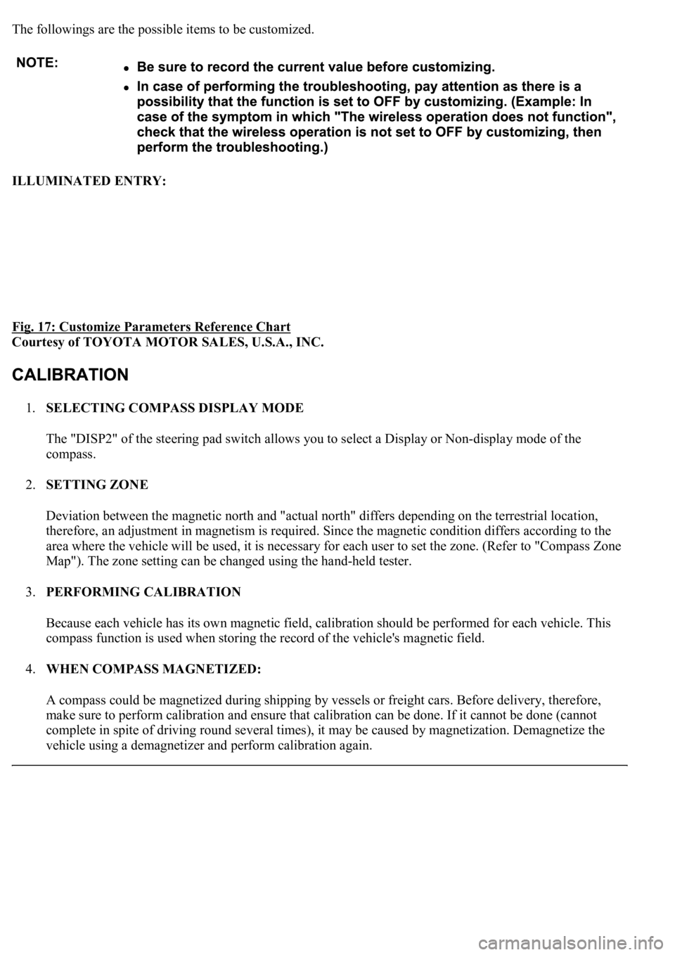
ILLUMINATED ENTRY:
Fig. 17: Customize Parameters Reference Chart
Courtesy of TOYOTA MOTOR SALES, U.S.A., INC.
1.SELECTING COMPASS DISPLAY MODE
The "DISP2" of the steering pad switch allows you to select a Display or Non-display mode of the
compass.
2.SETTING ZONE
Deviation between the magnetic north and "actual north" differs depending on the terrestrial location,
therefore, an adjustment in magnetism is required. Since the magnetic condition differs according to the
area where the vehicle will be used, it is necessary for each user to set the zone. (Refer to "Compass Zone
Map"). The zone setting can be changed using the hand-held tester.
3.PERFORMING CALIBRATION
Because each vehicle has its own magnetic field, calibration should be performed for each vehicle. This
compass function is used when storing the record of the vehicle's magnetic field.
4.WHEN COMPASS MAGNETIZED:
A compass could be magnetized during shipping by vessels or freight cars. Before delivery, therefore,
make sure to perform calibration and ensure that calibration can be done. If it cannot be done (cannot
complete in spite of driving round several times), it may be caused by magnetization. Demagnetize the
vehicle usin
g a demagnetizer and perform calibration again.
Page 1755 of 4500
Fig. 19: Identifying Zone Setting Number
Courtesy of TOYOTA MOTOR SALES, U.S.A., INC.
8.CALIBRATION SETTING MODE
a. Keep pressing the "RESET" for 6 sec. after selection of the compass display mode will activate the
calibration setting mode.
b. Drive the vehicle at a slow speed of 8 km/h (5 MPH) or less in the circular direction.
c. Driving round the circle 1 to 3 times will display the azimuthal direction on the display, completing
the calibration.
d. To finish the calibration mode, press the DISP2 switch long when the calibration is finished or
during the calibration.
HINT:
Page 2434 of 4500
Fig. 6: Dynamic Laser Cruise Control System Control Example Chart
Courtesy of TOYOTA MOTOR SALES, U.S.A., INC.
Setting of the vehicle distance can be changed to 3 distances by operating the distance control
switch (DISP2 button): long (approximately 75 m (246 ft)), middle (approximately 50 m (164 ft)),
and short (approximately 30 m (98 ft)) when vehicle speed is approximately 90 km/h (55 mph).
HINT:
Vehicle distance increases and decreases in accordance with vehicle speed.
Controlling condition is indicated on the combination meter multi-information display.
2.FUNCTION OF MAIN COMPONENTS
Page 2449 of 4500
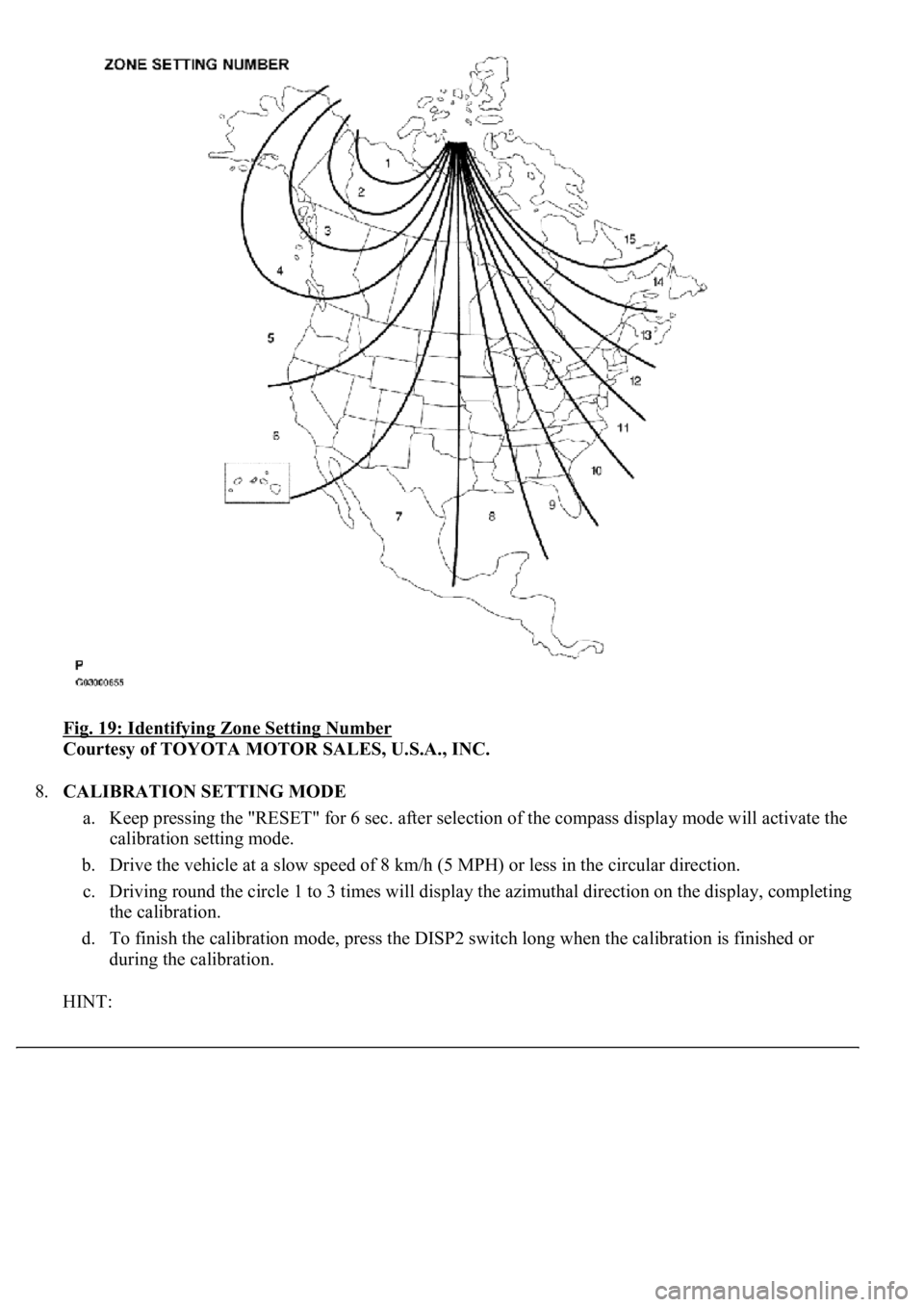
Fig. 17: [Display NORM]
Courtesy of TOYOTA MOTOR SALES, U.S.A., INC.
3.INSPECT STEERING PAD SWITCH ASSY
a. Turn the ignition switch to the ON position.
b. Push on the ON-OFF button of the cruise control main switch.
c. Push on the distance control switch (DISP2) of the steering pad switch.
d. Check that the indication of vehicle-to-vehicle distance, which is shown in the multi-information
displa
y on the combination meter, changes from "LONG", "MIDDLE" to "SHORT" in that order.


![LEXUS LS430 2003 Factory Repair Manual Fig. 17: [Display NORM]
Courtesy of TOYOTA MOTOR SALES, U.S.A., INC.
3.INSPECT STEERING PAD SWITCH ASSY
a. Turn the ignition switch to the ON position.
b. Push on the ON-OFF button of the cruise](/manual-img/36/57050/w960_57050-2448.png "LEXUS LS430 2003 Factory Repair Manual Fig. 17: [Display NORM]
Courtesy of TOYOTA MOTOR SALES, U.S.A., INC.
3.INSPECT STEERING PAD SWITCH ASSY
a. Turn the ignition switch to the ON position.
b. Push on the ON-OFF button of the cruise")