Page 4082 of 4500

3.INSPECT BATTERY VOLTAGE
Standard: 11 to 14 V
If voltage is below 11 V, recharge the battery before proceeding.
1.DATA LIST
HINT:
Using the hand-held tester's DATA LIST allows switch, sensor, actuator and other item values to be read
without removing any parts. Reading the DATA LIST early in troubleshooting is one way to save time.
a. Connect the hand-held tester (with CAN VIM) to the DLC3.
b. Turn the ignition switch ON.
c. Read the DATA LIST on the tester's screen.
Driver side J/B ECU:
DRIVER SIDE J/B ECU
2.ACTIVE TEST
HINT:
Performing the hand-held tester's ACTIVE TEST allows relay, VSV, actuator and other items to be
operated without removing any parts. Performing the ACTIVE TEST early in troubleshooting is one way
to save time. The DATA LIST can be displayed during the ACTIVE TEST.
a. Connect the hand-held tester (with CAN VIM) to the DLC3.
b. Turn the ignition switch ON.
c. Perform the ACTIVE TEST accordin
g to the display on the tester.
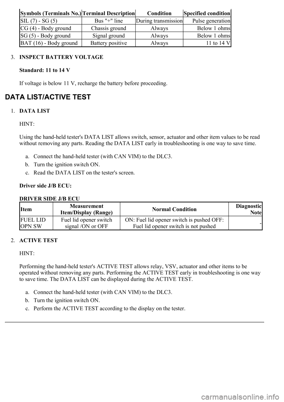
Symbols (Terminals No.)Terminal DescriptionConditionSpecified condition
SIL (7) - SG (5)Bus "+" lineDuring transmissionPulse generation
CG (4) - Body groundChassis groundAlwaysBelow 1 ohms
SG (5) - Body groundSignal groundAlwaysBelow 1 ohms
BAT (16) - Body groundBattery positiveAlways11 to 14 V
ItemMeasurement
Item/Display (Range)Normal ConditionDiagnostic
Note
FUEL LID
OPN SWFuel lid opener switch
signal /ON or OFFON: Fuel lid opener switch is pushed OFF:
Fuel lid opener switch is not pushed-
Page 4100 of 4500
Fig. 2: Fuel System - System Diagram (1 Of 3)
Courtesy of TOYOTA MOTOR SALES, U.S.A., INC.
Fuel s
ystem is determined by the ECM based on signals from various sensors.
Page 4211 of 4500

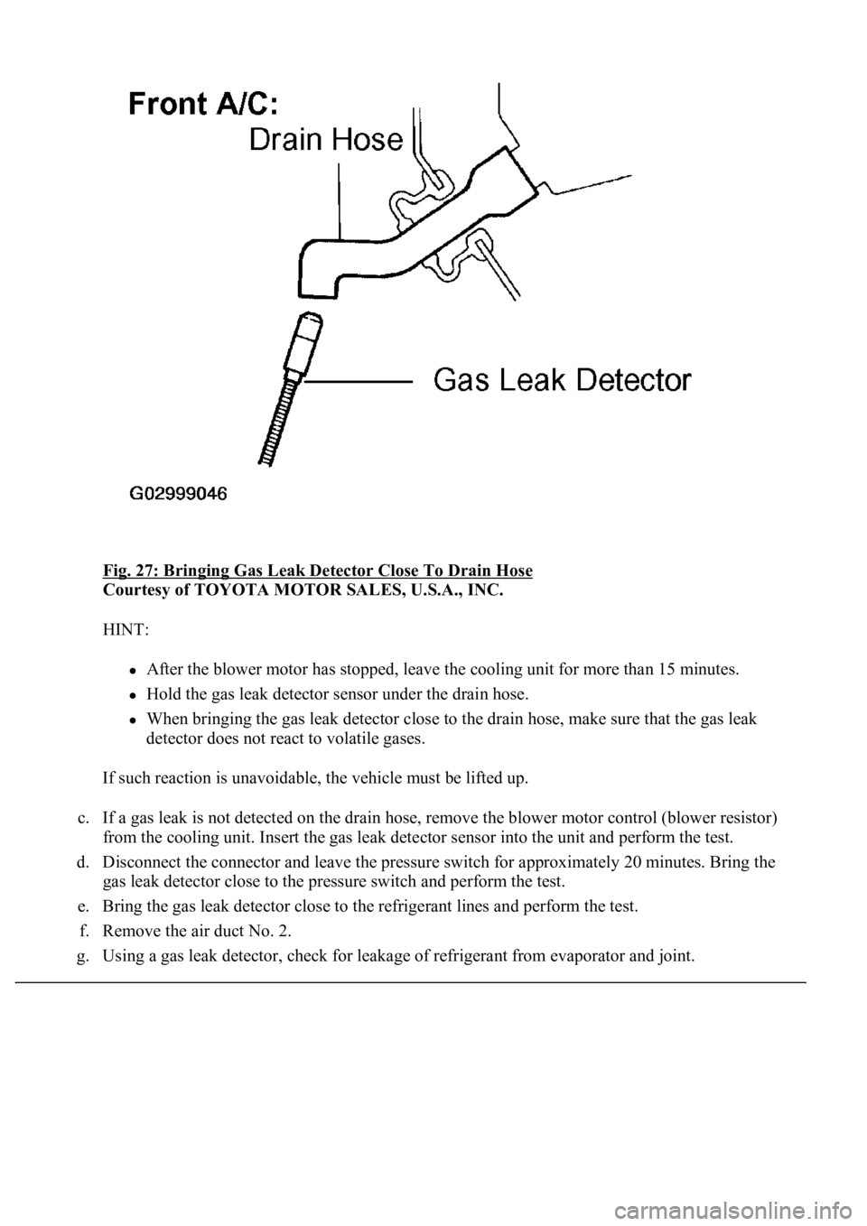
Fig. 27: Bringing Gas Leak Detector Close To Drain Hose
Courtesy of TOYOTA MOTOR SALES, U.S.A., INC.
HINT:
<0024004900570048005500030057004b004800030045004f0052005a004800550003005000520057005200550003004b0044005600030056005700520053005300480047000f0003004f004800440059004800030057004b00480003004600520052004f00
4c0051004a000300580051004c005700030049005200550003[more than 15 minutes.
Hold the gas leak detector sensor under the drain hose.
When bringing the gas leak detector close to the drain hose, make sure that the gas leak
detector does not react to volatile gases.
If such reaction is unavoidable, the vehicle must be lifted up.
c. If a gas leak is not detected on the drain hose, remove the blower motor control (blower resistor)
from the cooling unit. Insert the gas leak detector sensor into the unit and perform the test.
d. Disconnect the connector and leave the pressure switch for approximately 20 minutes. Bring the
gas leak detector close to the pressure switch and perform the test.
e. Bring the gas leak detector close to the refrigerant lines and perform the test.
f. Remove the air duct No. 2.
g.Using a gas leak detector, check for leakage of refrigerant from evaporator and joint.
Page 4227 of 4500

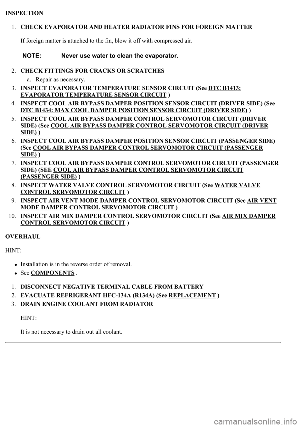
INSPECTION
1.CHECK EVAPORATOR AND HEATER RADIATOR FINS FOR FOREIGN MATTER
If foreign matter is attached to the fin, blow it off with compressed air.
2.CHECK FITTINGS FOR CRACKS OR SCRATCHES
a. Repair as necessary.
3.INSPECT EVAPORATOR TEMPERATURE SENSOR CIRCUIT (See DTC B1413:
EVAPORATOR TEMPERATURE SENSOR CIRCUIT )
4.INSPECT COOL AIR BYPASS DAMPER POSITION SENSOR CIRCUIT (DRIVER SIDE) (See
DTC B1434: MAX COOL DAMPER POSITION SENSOR CIRCUIT (DRIVER SIDE)
)
5.INSPECT COOL AIR BYPASS DAMPER CONTROL SERVOMOTOR CIRCUIT (DRIVER
SIDE) (See COOL AIR BYPASS DAMPER CONTROL SERVOMOTOR CIRCUIT (DRIVER
SIDE) )
6.INSPECT COOL AIR BYPASS DAMPER POSITION SENSOR CIRCUIT (PASSENGER SIDE)
(See COOL AIR BYPASS DAMPER CONTROL SERVOMOTOR CIRCUIT (PASSENGER
SIDE) )
7.INSPECT COOL AIR BYPASS DAMPER CONTROL SERVOMOTOR CIRCUIT (PASSENGER
SIDE) (SEE COOL AIR BYPASS DAMPER CONTROL SERVOMOTOR CIRCUIT
(PASSENGER SIDE) )
8.INSPECT WATER VALVE CONTROL SERVOMOTOR CIRCUIT (See WATER VALVE
CONTROL SERVOMOTOR CIRCUIT )
9.INSPECT AIR VENT MODE DAMPER CONTROL SERVOMOTOR CIRCUIT (See AIR VENT
MODE DAMPER CONTROL SERVOMOTOR CIRCUIT )
10.INSPECT AIR MIX DAMPER CONTROL SERVOMOTOR CIRCUIT (See AIR MIX DAMPER
CONTROL SERVOMOTOR CIRCUIT )
OVERHAUL
HINT:
Installation is in the reverse order of removal.
See COMPONENTS .
1.DISCONNECT NEGATIVE TERMINAL CABLE FROM BATTERY
2.EVACUATE REFRIGERANT HFC-134A (R134A) (See REPLACEMENT
)
3.DRAIN ENGINE COOLANT FROM RADIATOR
HINT:
It is not necessar
y to drain out all coolant.
Page 4238 of 4500
Fig. 52: Removing Evaporator Cover
Courtesy of TOYOTA MOTOR SALES, U.S.A., INC.
20.REMOVE EVAPORATOR TEMPERATURE SENSOR
21.REMOVE HEATER RADIATOR UNIT SUB-ASSY
a. Remove the screw and clamp.
b. Remove the 2 screws, 2 clamps and heater radiator pipes.
c. Remove the 2 O-rings from the heater radiator pipes.
d. Pull out the heater radiator unit sub-assy.
Page 4277 of 4500
Fig. 89: Disconnecting Liquid Tube Sub-Assy A
Courtesy of TOYOTA MOTOR SALES, U.S.A., INC.
7.REMOVE HIGH PITCHED HORN ASSY (See REPLACEMENT
)
8.REMOVE LOW PITCHED HORN ASSY (See REPLACEMENT
)
9.REMOVE SMOG VENTILATION SENSOR
a. Disconnect the connector.
b. Remove the bolt and smog ventilation sensor.
Page 4278 of 4500
Fig. 90: Removing Smog Ventilation Sensor Bolt
Courtesy of TOYOTA MOTOR SALES, U.S.A., INC.
10.REMOVE HOOD LOCK ASSY
a. Remove the 2 bolts, nut and hood lock ass
y.
Page 4295 of 4500
INSPECTION
1.INSPECT REAR BLOWER MOTOR CIRCUIT (See REAR BLOWER MOTOR CIRCUIT
)
2.EXHAUST DAMPER CONTROL SERVOMOTOR CIRCUIT (See EXHAUST DAMPER
CONTROL SERVOMOTOR CIRCUIT )
3.INSPECT REAR MAGNETIC VALVE CIRCUIT (See REAR MAGNETIC VALVE CIRCUIT
)
4.INSPECT SMOKE SENSOR CIRCUIT (See SMOKE SENSOR CIRCUIT
)
5.INSPECT EVAPORATOR SUB-ASSY (REAR)
a. Check the evaporator sub-assy (rear) fins for blockage.
If the fins are clogged, clean them with compressed air.
b. Check the fitting for cracks or scratches.
If necessary, repair or replace.
6.INSPECT COOLING BOX LAMP SUB-ASSY
a. Connect positive (+) lead to terminal 1 and negative (-) lead to terminal 2.
b. Check that the cooling box lamp sub-assy comes on.
If coolin
g box light does not come on, replace the cooling box lamp sub-assy.