Page 3759 of 4500

Courtesy of TOYOTA MOTOR SALES, U.S.A., INC.
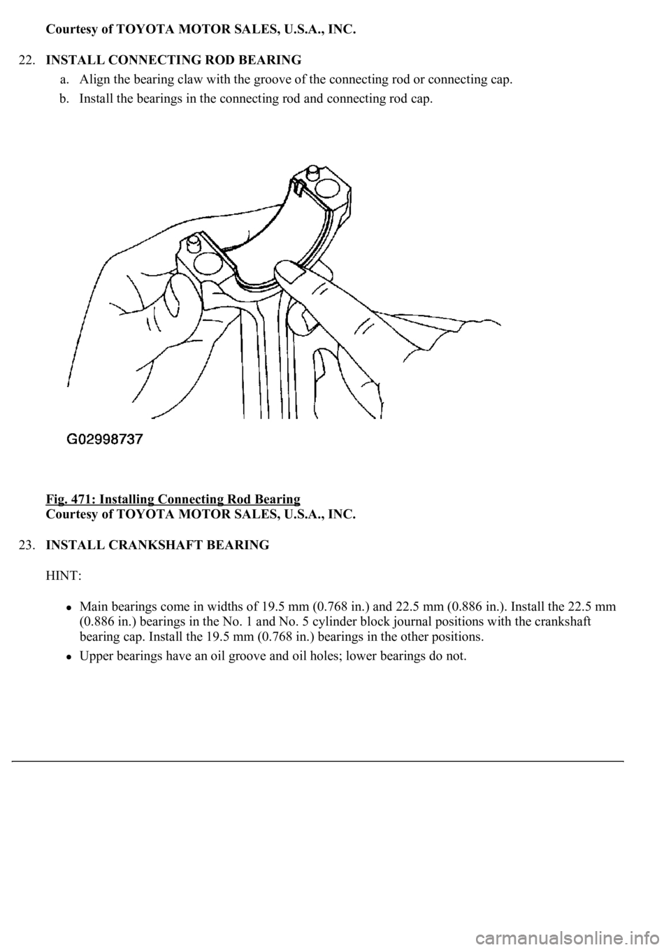
22.INSTALL CONNECTING ROD BEARING
a. Align the bearing claw with the groove of the connecting rod or connecting cap.
b. Install the bearings in the connecting rod and connecting rod cap.
Fig. 471: Installing Connecting Rod Bearing
Courtesy of TOYOTA MOTOR SALES, U.S.A., INC.
23.INSTALL CRANKSHAFT BEARING
HINT:
<00300044004c005100030045004800440055004c0051004a0056000300460052005000480003004c00510003005a004c00470057004b005600030052004900030014001c001100180003005000500003000b00130011001a0019001b0003004c0051001100
0c000300440051004700030015001500110018000300500050[ (0.886 in.). Install the 22.5 mm
(0.886 in.) bearings in the No. 1 and No. 5 cylinder block journal positions with the crankshaft
<0045004800440055004c0051004a000300460044005300110003002c0051005600570044004f004f00030057004b004800030014001c001100180003005000500003000b00130011001a0019001b0003004c00510011000c00030045004800440055004c00
51004a00560003004c005100030057004b0048000300520057[her positions.
Upper bearings have an oil groove and oil holes; lower bearings do not.
Page 3760 of 4500
Fig. 472: Identifying Upper Bearings And Lower Bearings Oil Groove
Courtesy of TOYOTA MOTOR SALES, U.S.A., INC.
a. Align the bearing claw with the claw groove of the cylinder block, and push in the 5 upper
bearings.
Page 3762 of 4500
Fig. 474: Identifying Bearing Cap Installation Position
Courtesy of TOYOTA MOTOR SALES, U.S.A., INC.
24.INSTALL CRANKSHAFT THRUST WASHER SET
a. Install the 2 thrust washers under the No. 3 journal position of the cylinder block with the oil
grooves facing outward.
Page 3764 of 4500
Fig. 476: Identifying No. 3 Bearing Cap With The Grooves
Courtesy of TOYOTA MOTOR SALES, U.S.A., INC.
25.INSTALL CRANKSHAFT
a. Place the crankshaft on the cylinder block.
b. Install the 5 crankshaft bearing caps in their proper locations.
Page 3774 of 4500
connecting rod cap bolts.
3. Mark the front of the connecting cap bolt with paint.
4. Retighten the cap bolts 90° as shown in the illustration.
5. Check that the painted mark is now at a 90° angle to the front.
d. Check that the crankshaft turns smoothly.
e. Check the connecting rod thrust clearance (see step 2).
27.INSTALL WATER SEAL PLATE
a. Remove any old packing (FIPG) material and be careful not to drop any oil on the contact surfaces
of the seal plate and cylinder block.
Fig. 486: Identifying Painted Mark
Courtesy of TOYOTA MOTOR SALES, U.S.A., INC.
Using a razor blade and gasket scraper, remove all the old packing (FIPG) material from the
gasket surfaces and sealing groove.
Thoroughly clean all components to remove all loose material.
Using a non-residue solvent, clean both sealing surfaces.
b. Apply seal packing to the seal plate as shown in the illustration.
Seal packing: Part No. 08826-00080 or equivalent
Page 3775 of 4500
<002c0051005600570044004f004f00030044000300510052005d005d004f004800030057004b004400570003004b00440056000300450048004800510003004600580057000300570052000300440003001500030057005200030016000300500050000300
0b001300110013001b00030057005200030013001100140015[ in.) opening.
Parts must be assembled within 5 minutes of application. Otherwise the material must be
removed and reapplied.
Immediately remove the nozzle from the tube and reinstall the cap.
c. Install the seal plate with the 2 nuts. Alternately tighten the nuts in several passes.
Torque: 14 N.m (143 kgf.cm, 10 ft.lbf)
Fig. 487: Applying Seal Packing
Courtesy of TOYOTA MOTOR SALES, U.S.A., INC.
28.INSTALL CYLINDER BLOCK WATER DRAIN COCK SUB-ASSY
a. Apply seal packing to 2 or 3 threads.
Seal packing: Part No. 08826-00100 or equivalent
Page 3776 of 4500
Fig. 488: Applying Seal Packing
Courtesy of TOYOTA MOTOR SALES, U.S.A., INC.
b. Install the RH and LH drain unions.
Torque: 49 N.m (500 kgf.cm, 36 ft.lbf)
HINT:
After appl
ying the specified torque, rotate the drain union clockwise until its drain port is facing forward.
Page 3780 of 4500

1.REMOVE FRONT FLOOR BRACE CENTER
a. Remove the 4 bolts and floor brace.
2.Bank 1, 2 sensor 2:
REMOVE HEATED OXYGEN SENSOR
a. Remove the 2 sensors.
3.REMOVE EXHAUST PIPE ASSY FRONT
a. Loosen the clamp.
b. Remove the 4 bolts, 4 nuts, pipe and 2 gaskets.
4.REMOVE EXHAUST PIPE ASSY CENTER
a. Loosen the 2 clamps.
b. Remove the pipe.
5.REMOVE EXHAUST PIPE ASSY TAIL (LH)
a. Remove the pipe from the 3 rings.
6.REMOVE EXHAUST PIPE ASSY TAIL (RH)
a. Remove the pipe from the 3 rings.
7.INSTALL EXHAUST PIPE ASSY FRONT
a. Install the 2 new gaskets to the pipe.
b. Install the pipe to the TWC with the 4 bolts and 4 nuts.
Torque: 44 N.m (450 kgf.cm, 32 ft.lbf)
8.Bank 1, 2 sensor 2:
INSTALL HEATED OXYGEN SENSOR
a. Install the 2 sensors.
Torque: 44 N.m (450 kgf.cm, 32 ft.lbf)
HINT:
Before installing the sensor, twist the sensor wire counterclockwise 3 and 1/2 turns.
After installing the sensor, check that the sensor wire is not twisted. If it is twisted, remove the
sensor and reinstall it.
9.INSTALL EXHAUST PIPE ASSY CENTER
a. Install the pipe.
b. Tighten the clamp.
Standard dimension (A): 13 to 15 mm (0.51 to 0.59 in.)