Page 3692 of 4500
Thoroughly clean all parts to be assembled.
Before installing the parts, apply new engine oil to all sliding and rotating surfaces.
Replace all gaskets, O-rings and oil seals with new parts.
1.REMOVE CYLINDER BLOCK DRAIN COCK SUB-ASSY AND WATER SEAL PLATE
a. Remove the 2 nuts and seal plate.
b. Remove the RH and LH drain unions.
Fig. 408: Identifying Seal Plate
Courtesy of TOYOTA MOTOR SALES, U.S.A., INC.
Page 3753 of 4500
Fig. 465: Heating Piston
Courtesy of TOYOTA MOTOR SALES, U.S.A., INC.
c. Coat the piston pin with engine oil.
d. The piston's front mark and the connecting rod's outside mark should face the same direction, as
shown in the illustration.
e. Align the piston pin holes of the piston and connecting rod, and push in the piston pin with your
thumb.
Page 3766 of 4500
Fig. 478: Placing Bearing Caps Level
Courtesy of TOYOTA MOTOR SALES, U.S.A., INC.
c. Install the crankshaft bearing cap bolts.
HINT:
The bearing cap bolts are tightened in 2 progressive steps (steps (2) and (4)).
If any one of the bearing cap bolts is broken or deformed, replace it.
1. Apply a light coat of engine oil on the threads and under the crankshaft bearing cap bolts.
2. Install and uniformly tighten the 20 crankshaft bearing cap bolts in several passes in the
sequence shown in the illustration.
Page 3773 of 4500
Fig. 484: Identifying Outside Mark Of Connecting Rod Cap
Courtesy of TOYOTA MOTOR SALES, U.S.A., INC.
c. Install the connecting rod cap bolts.
HINT:
The connecting rod cap bolts are tightened in 2 progressive steps (see steps (2) and (4)).
If any one of the connecting rod cap bolts is broken or deformed, replace it.
1. Apply a light coat of engine oil on the threads and under the heads of the connecting rod cap
bolts.
2. Install and alternately tighten the 2 connecting rod cap bolts in several passes.
Fig. 485: Tightening Connecting Rod Cap Bolts
Courtesy of TOYOTA MOTOR SALES, U.S.A., INC.
Torque: 24.5 N.m (250 kgf.cm, 18 ft.lbf)
If an
y one of the connecting rod cap bolts does not meet the torque specification, replace the
Page 3967 of 4500
OPERATION AND TILT AND TELESCOPIC POSITION OPERATION
HINT:
*1: Wireless door lock control system
*2: Smart key system
If the result is not as specified, inspect the tilt and telescopic.
4.CHECK FRONT POWER SEAT FUNCTION
a. Check the basic functions.
1. Operate the power seat switches and check to make sure each seat function works:
Sliding
Front vertical
Lifter
Reclining
Lumbar support
Cushion sliding
Headrest
OperationTilt and Telescopic Position Operation
Key is inserted to the key cylinder*1 Engine switch is
pushed*2Vertical tilt position
Key is inserted to the key cylinder*1 Engine switch is
pushed*2Telescopic flexibility (lengthening and
shortening)
Page 4021 of 4500
Fig. 29: Connecting Connector
Courtesy of TOYOTA MOTOR SALES, U.S.A., INC.
14.INSTALL FRONT SHOCK ABSORBER CAP LH
a. Install the front shock absorber cap LH with 3 nuts.
Torque: 58 N.m (590 kgf.cm, 43 ft.lbf)
b. Start the engine to fill the pneumatic front LH w/shock absorber cylinder assy with air.
Page 4103 of 4500

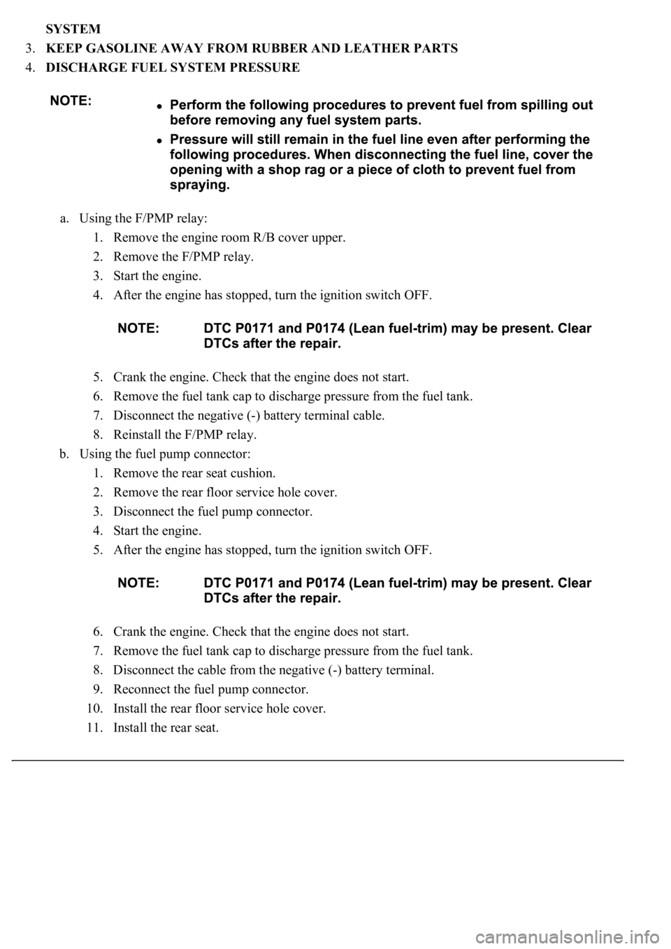
SYSTEM
3.KEEP GASOLINE AWAY FROM RUBBER AND LEATHER PARTS
4.DISCHARGE FUEL SYSTEM PRESSURE
a. Using the F/PMP relay:
1. Remove the engine room R/B cover upper.
2. Remove the F/PMP relay.
3. Start the engine.
4. After the engine has stopped, turn the ignition switch OFF.
5. Crank the engine. Check that the engine does not start.
6. Remove the fuel tank cap to discharge pressure from the fuel tank.
7. Disconnect the negative (-) battery terminal cable.
8. Reinstall the F/PMP relay.
b. Using the fuel pump connector:
1. Remove the rear seat cushion.
2. Remove the rear floor service hole cover.
3. Disconnect the fuel pump connector.
4. Start the engine.
5. After the engine has stopped, turn the ignition switch OFF.
6. Crank the engine. Check that the engine does not start.
7. Remove the fuel tank cap to discharge pressure from the fuel tank.
8. Disconnect the cable from the negative (-) battery terminal.
9. Reconnect the fuel pump connector.
10. Install the rear floor service hole cover.
11. Install the rear seat.
Page 4105 of 4500
33 N.m (340 kgf.cm, 24 ft.lbf) for use with SST
39 N.m (400 kgf.cm, 29 ft.lbf)
Fig. 6: Tightening Union Bolt To Specified Torque
Courtesy of TOYOTA MOTOR SALES, U.S.A., INC.
HINT:
Use a torque wrench with a fulcrum length of 30 cm (11.81 in.).
c. Observe these precautions when removing and installing the injector.
1. Never reuse the O-ring.
2. When placing a new O-ring on the injector, take care not to damage it.
3. Coat a new O-ring with spindle oil or gasoline before installing. Never use engine, gear or
brake oil.