Page 4177 of 4500

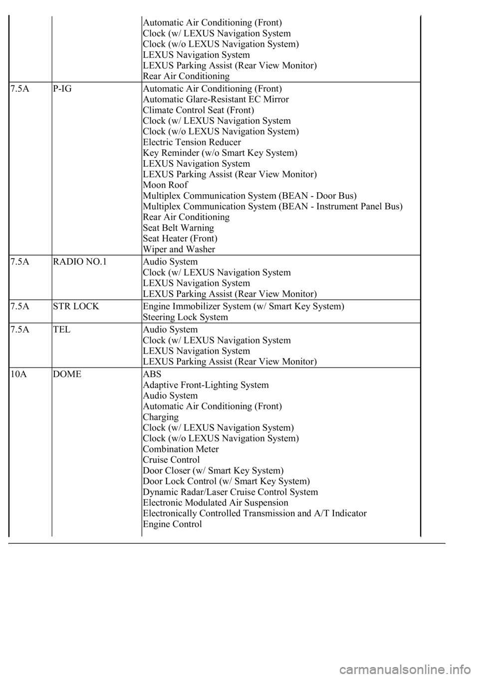
Automatic Air Conditioning (Front)
Clock (w/ LEXUS Navigation System
Clock (w/o LEXUS Navigation System)
LEXUS Navigation System
LEXUS Parking Assist (Rear View Monitor)
Rear Air Conditioning
7.5AP-IGAutomatic Air Conditioning (Front)
Automatic Glare-Resistant EC Mirror
Climate Control Seat (Front)
Clock (w/ LEXUS Navigation System
Clock (w/o LEXUS Navigation System)
Electric Tension Reducer
Key Reminder (w/o Smart Key System)
LEXUS Navigation System
LEXUS Parking Assist (Rear View Monitor)
Moon Roof
Multiplex Communication System (BEAN - Door Bus)
Multiplex Communication System (BEAN - Instrument Panel Bus)
Rear Air Conditioning
Seat Belt Warning
Seat Heater (Front)
Wiper and Washer
7.5ARADIO NO.1Audio System
Clock (w/ LEXUS Navigation System
LEXUS Navigation System
LEXUS Parking Assist (Rear View Monitor)
7.5ASTR LOCKEngine Immobilizer System (w/ Smart Key System)
Steering Lock System
7.5ATELAudio System
Clock (w/ LEXUS Navigation System
LEXUS Navigation System
LEXUS Parking Assist (Rear View Monitor)
10ADOMEABS
Adaptive Front-Lighting System
Audio System
Automatic Air Conditioning (Front)
Charging
Clock (w/ LEXUS Navigation System)
Clock (w/o LEXUS Navigation System)
Combination Meter
Cruise Control
Door Closer (w/ Smart Key System)
Door Lock Control (w/ Smart Key System)
Dynamic Radar/Laser Cruise Control System
Electronic Modulated Air Suspension
Electronically Controlled Transmission and A/T Indicator
Engine Control
Page 4195 of 4500
compressor burnout may occur. Necessary care should be taken to avoid this.
Fig. 3: Identifying Precaution Operating Compressor
Courtesy of TOYOTA MOTOR SALES, U.S.A., INC.
7.DO NOT OPEN HIGH PRESSURE MANIFOLD VALVE WHILE COMPRESSOR IS
OPERATING
If the high pressure valves are opened, refrigerant flows in the reverse direction and could cause the
charging cylinder to rupture. Open and close only the low pressure valve.
8.BE CAREFUL NOT TO OVERCHARGE SYSTEM WITH REFRIGERANT
If refrigerant is overcharged, it causes problems such as insufficient cooling, poor fuel economy, engine
Page 4196 of 4500
overheating etc.
9.DO NOT OPERATE ENGINE AND COMPRESSOR WITH NO REFRIGERANT
10.SUPPLEMENTAL RESTRAINT SYSTEM (SRS)
The LEXUS LS430 is equipped with an SRS (Supplemental Restraint system) such as the driver, front
passenger, side, curtain shield air bags etc.. Failure to carry out service operation in the correct sequence
could cause the SRS to unexpectedly deploy during servicing, possibly leading to a serious accident.
Before servicing (including removal or installation of parts, inspection or replacement), be sure to read
the precautionary notices in PRECAUTION
.
11.PRECAUTION FOR DISCONNECTING THE BATTERY CABLE
DISCONNECTING BATTERY CABLE
LOCATION
System NameProceed To
Front Power Seat Control SystemINITIALIZATION
Page 4199 of 4500
ON-VEHICLE INSPECTION
1.INSPECT REFRIGERANT VOLUME
a. Check the sight glass on the liquid tube.
Test conditions:
Engine is running at 1,500 rpm
Single A/C:
Blower speed control switch at "HI" position
Dual A/C:
Front blower switch at "HI" position
Rear blower switch at "HI" position
A/C switch ON
Single A/C:
Temperature control switch at "MAX. COOL" position
Dual A/C:
Rear temperature control switch at "MAX. COOL" position
Front driver side temperature control switch at "MAX. COOL" position
Front passenger side temperature control switch at "MAX. COOL" position
Fully open the doors
Page 4201 of 4500
2.INSPECT REFRIGERANT PRESSURE WITH MANIFOLD GAUGE SET
a. This is a method in which trouble is located by using a manifold gauge set. Read the manifold
gauge pressure when these conditions are established.
Test conditions:
Temperature at the air inlet with the switch set at RECIRC is 30 to 35°C (86 to 95°F)
Engine is running at 2,000 rpm
Blower speed control switch is at "HI"
Temperature control dial is at "COOL"
HINT:
It should be noted that the gauge indications may vary slightly due to ambient temperature
conditions.
1. Normally functioning refrigeration system
Gauge reading:
Low pressure side: 0.15 to 0.25 MPa (1.5 to 2.5 kgf/cm
2 )
High pressure side: 1.37 to 1.57 MPa (14 to 16 kgf/cm
2 )
Page 4209 of 4500

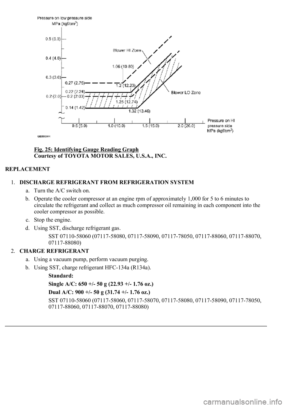
Fig. 25: Identifying Gauge Reading Graph
Courtesy of TOYOTA MOTOR SALES, U.S.A., INC.
REPLACEMENT
1.DISCHARGE REFRIGERANT FROM REFRIGERATION SYSTEM
a. Turn the A/C switch on.
b. Operate the cooler compressor at an engine rpm of approximately 1,000 for 5 to 6 minutes to
circulate the refrigerant and collect as much compressor oil remaining in each component into the
cooler compressor as possible.
c. Stop the engine.
d. Using SST, discharge refrigerant gas.
<00360036003700030013001a00140014001300100018001b0013001900130003000b0013001a00140014001a00100018001b0013001b0013000f00030013001a00140014001a00100018001b0013001c0013000f00030013001a00140014001a0010001a00
1b001300180013000f00030013001a00140014001a0010001b[8060, 07117-88070,
07117-88080)
2.CHARGE REFRIGERANT
a. Using a vacuum pump, perform vacuum purging.
b. Using SST, charge refrigerant HFC-134a (R134a).
Standard:
Single A/C: 650 +/- 50 g (22.93 +/- 1.76 oz.)
Dual A/C: 900 +/- 50 g (31.74 +/- 1.76 oz.)
<00360036003700030013001a00140014001300100018001b0013001900130003000b0013001a00140014001a00100018001b001300190013000f00030013001a00140014001a00100018001b0013001a0013000f00030013001a00140014001a0010001800
1b0013001b0013000f00030013001a00140014001a00100018[8090, 07117-78050,
07117-88060, 07117-88070, 07117-88080)
Page 4210 of 4500
Fig. 26: Height Pressure To Refrigerant Amount Graph
Courtesy of TOYOTA MOTOR SALES, U.S.A., INC.
3.WARM UP ENGINE
4.INSPECT FOR REFRIGERANT LEAKAGE
a. Perform in these conditions:
Stop the engine.
Secure good ventilation (the gas leak detector may not react to volatile gases which are not
refrigerant, such as evaporated gasoline and exhaust gas).
Repeat the test 2 or 3 times.
Make sure that there is some refrigerant remaining in the refrigeration system.
When compressor is off: approx. 392 to 588 kPa (4 to 6 kgf/cm
2 , 57 to 85 psi)
b. Bring the gas leak detector close to the drain hose before performing the test.
Page 4227 of 4500

INSPECTION
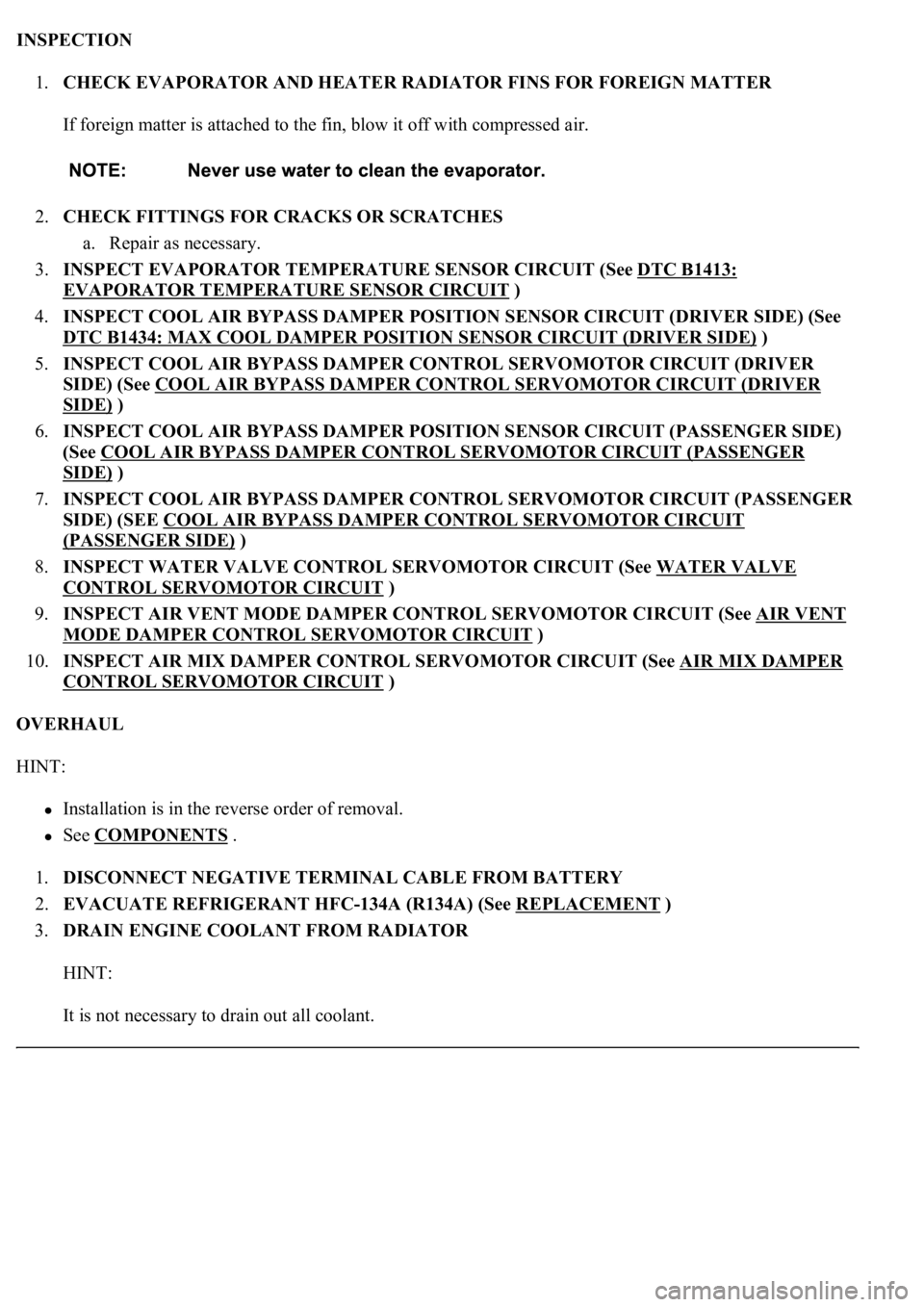
1.CHECK EVAPORATOR AND HEATER RADIATOR FINS FOR FOREIGN MATTER
If foreign matter is attached to the fin, blow it off with compressed air.
2.CHECK FITTINGS FOR CRACKS OR SCRATCHES
a. Repair as necessary.
3.INSPECT EVAPORATOR TEMPERATURE SENSOR CIRCUIT (See DTC B1413:
EVAPORATOR TEMPERATURE SENSOR CIRCUIT )
4.INSPECT COOL AIR BYPASS DAMPER POSITION SENSOR CIRCUIT (DRIVER SIDE) (See
DTC B1434: MAX COOL DAMPER POSITION SENSOR CIRCUIT (DRIVER SIDE)
)
5.INSPECT COOL AIR BYPASS DAMPER CONTROL SERVOMOTOR CIRCUIT (DRIVER
SIDE) (See COOL AIR BYPASS DAMPER CONTROL SERVOMOTOR CIRCUIT (DRIVER
SIDE) )
6.INSPECT COOL AIR BYPASS DAMPER POSITION SENSOR CIRCUIT (PASSENGER SIDE)
(See COOL AIR BYPASS DAMPER CONTROL SERVOMOTOR CIRCUIT (PASSENGER
SIDE) )
7.INSPECT COOL AIR BYPASS DAMPER CONTROL SERVOMOTOR CIRCUIT (PASSENGER
SIDE) (SEE COOL AIR BYPASS DAMPER CONTROL SERVOMOTOR CIRCUIT
(PASSENGER SIDE) )
8.INSPECT WATER VALVE CONTROL SERVOMOTOR CIRCUIT (See WATER VALVE
CONTROL SERVOMOTOR CIRCUIT )
9.INSPECT AIR VENT MODE DAMPER CONTROL SERVOMOTOR CIRCUIT (See AIR VENT
MODE DAMPER CONTROL SERVOMOTOR CIRCUIT )
10.INSPECT AIR MIX DAMPER CONTROL SERVOMOTOR CIRCUIT (See AIR MIX DAMPER
CONTROL SERVOMOTOR CIRCUIT )
OVERHAUL
HINT:
Installation is in the reverse order of removal.
See COMPONENTS .
1.DISCONNECT NEGATIVE TERMINAL CABLE FROM BATTERY
2.EVACUATE REFRIGERANT HFC-134A (R134A) (See REPLACEMENT
)
3.DRAIN ENGINE COOLANT FROM RADIATOR
HINT:
It is not necessar
y to drain out all coolant.