Page 1005 of 4500
34.CHECK AND ADJUST BRAKE PEDAL HEIGHT (SEE ON-VEHICLE INSPECTION )
35.CHECK PEDAL FREE PLAY (SEE ON
-VEHICLE INSPECTION )
36.CHECK PEDAL RESERVE DISTANCE (SEE ON
-VEHICLE INSPECTION )
37.INSTALL COMBINATION METER ASSY (SEE OVERHAUL
)
38.INSTALL INSTRUMENT CLUSTER FINISH PANEL (SEE REPLACEMENT
)
39.INSTALL INSTRUMENT PANEL UNDER COVER SUB-ASSY NO.2 (SEE REPLACEMENT
)
40.INSTALL INSTRUMENT PANEL AIR BAG ASSY LOWER NO.1 (SEE REPLACEMENT
)
41.INSTALL INSTRUMENT PANEL SAFETY PAD SUB-ASSY NO.1 (SEE REPLACEMENT
)
42.INSTALL OUTER MIRROR SWITCH ASSY
43.INSTALL COIN BOX ASSY
44.INSTALL INSTRUMENT PANEL UNDER COVER SUB-ASSY NO.1 (SEE REPLACEMENT
)
45.INSTALL INSTRUMENT CLUSTER FINISH PANEL CENTER LOWER
46.INSTALL INSTRUMENT CLUSTER FINISH PANEL END
47.INSTALL TURN SIGNAL SWITCH ASSY (SEE REPLACEMENT
)
48.INSTALL SPIRAL CABLE SUB-ASSY (SEE REPLACEMENT
)
49.INSTALL STEERING COLUMN COVER (SEE OVERHAUL
)
50.INSTALL STEERING WHEEL ASSY (SEE OVERHAUL
)
<00360036003700030013001c001c001800130010001800130013001400160003000b0013001c001c00180014001000130018001300140013000f00030013001c001c00180015001000130018001300140013000f00030013001c001c001800160010001300
18001300150013000f00030013001c001c0018001700100013[5021)
51.INSTALL HORN BUTTON ASSY (SEE OVERHAUL
)
52.INSTALL STEERING WHEEL COVER LOWER NO.2
53.INSTALL SWITCH & VOLUME CASE
54.CONNECT BATTERY NEGATIVE TERMINAL
55.INSPECT SRS WARNING LIGHT (SEE DIAGNOSIS SYSTEM
)
56.PERFORM INITIALIZATION (SEE PRECAUTION
)
OVERHAUL
1.REMOVE ENGINE ROOM SIDE COVER
2.SEPARATE ENGINE ROOM NO.3 R/B
a. Remove the bolt and separate the engine room No.3 R/B.
3.DRAIN BRAKE FLUID
a. Draw out fluid with syringe.
4.REMOVE BRAKE MASTER CYLINDER SUB-ASSY
a. Remove the clamp from the 2 brake tubes.
Page 1104 of 4500
Fig. 133: Connecting Yawrate Sensor Connector
Courtesy of TOYOTA MOTOR SALES, U.S.A., INC.
6.INSTALL REAR CONSOLE ARMREST ASSY (SEE REPLACEMENT
)
7.INSTALL CONSOLE BOX CARPET
8.INSTALL CONSOLE UPPER REAR PANEL SUB-ASSY (SEE REPLACEMENT
)
9.PERFORM YAWRATE SENSOR ZERO POINT CALIBRATION (SEE CALIBRATION
)
REPLACEMENT
1.(SEE PRECAUTION
)
2.SEPARATE BATTERY NEGATIVE TERMINAL (SEE PRECAUTION
)
3.PLACE FRONT WHEELS FACING STRAIGHT AHEAD
4.REMOVE HORN BUTTON ASSY (SEE OVERHAUL
)
5.REMOVE STEERING WHEEL ASSY (SEE OVERHAUL
)
<00360036003700030013001c001c001800130010001800130013001400160003000b0013001c001c00180014001000130018001300140013000f00030013001c001c00180015001000130018001300140013000f00030013001c001c001800160010001300
18001300150013000f00030013001c001c0018001700100013[5021)
6.REMOVE STEERING COLUMN COVER (SEE OVERHAUL
)
Page 1105 of 4500
7.REMOVE SPIRAL CABLE SUB-ASSY (SEE REPLACEMENT )
8.REMOVE STEERING SENSOR
a. Release 6 claw fittings and remove the steering sensor from the spiral cable.
Fig. 134: Removing Steering Sensor From Spiral Cable
Courtesy of TOYOTA MOTOR SALES, U.S.A., INC.
9.INSTALL STEERING SENSOR
a. Install the steering sensor to the spiral cable.
Page 1106 of 4500
Fig. 135: Installing Steering Sensor To Spiral Cable
Courtesy of TOYOTA MOTOR SALES, U.S.A., INC.
10.ADJUST CENTER FRONT WHEEL
11.INSTALL SPIRAL CABLE SUB-ASSY (SEE REPLACEMENT
)
12.CENTER SPIRAL CABLE (SEE REPLACEMENT
)
13.INSTALL STEERING COLUMN COVER
14.INSTALL STEERING WHEEL ASSY (SEE OVERHAUL
)
15.INSTALL HORN BUTTON ASSY (SEE OVERHAUL
)
16.INSPECT STEERING WHEEL CENTER POINT
17.INSPECT HORN BUTTON ASSY (SEE REPLACEMENT
)
18.INSPECT SRS WARNING LIGHT (SEE DIAGNOSIS SYSTEM
)
19.INSPECT ABS WARNING LIGHT AND VSC WARNING LIGHT (SEE DIAGNOSIS SYSTEM
)
PRECAUTION
Page 1129 of 4500

REPLACEMENT
1.DISCONNECT BATTERY NEGATIVE TERMINAL (SEE PRECAUTION
)
2.REMOVE SEAT BELT ANCHOR COVER CAP LH
3.REMOVE SEAT TRACK COVER RH
4.REMOVE SEAT TRACK OUTER COVER LH
5.REMOVE SEAT TRACK BRACKET COVER OUTER FRONT
6.REMOVE SEAT TRACK BRACKET COVER INNER FRONT
7.REMOVE FRONT SEAT ASSY LH (SEE OVERHAUL
)
8.REMOVE INSTRUMENT CLUSTER FINISH PANEL END
9.REMOVE INSTRUMENT CLUSTER FINISH PANEL CENTER LOWER (SEE
REPLACEMENT
)
10.REMOVE INSTRUMENT PANEL UNDER COVER SUB-ASSY NO.1 (SEE REPLACEMENT
)
11.REMOVE COIN BOX ASSY
12.REMOVE OUTER MIRROR SWITCH ASSY
13.REMOVE INSTRUMENT PANEL SAFETY PAD SUB-ASSY NO.1 (SEE REPLACEMENT
)
14.REMOVE INSTRUMENT PANEL AIR BAG ASSY LOWER NO.1 (SEE REPLACEMENT
)
15.REMOVE INSTRUMENT PANEL UNDER COVER SUB-ASSY NO.2 (SEE REPLACEMENT
)
16.REMOVE INSTRUMENT PANEL GARNISH SUB-ASSY LH (SEE REPLACEMENT
)
17.REMOVE GLOVE COMPARTMENT PLATE (SEE REPLACEMENT
)
18.REMOVE CHOKE KNOB HOLE COVER (SEE REPLACEMENT
)
19.REMOVE INSTRUMENT PANEL FINISH PANEL (SEE REPLACEMENT
)
20.REMOVE FRONT DOOR SCUFF PLATE LH (LHD STEERING POSITION TYPE) (SEE
REPLACEMENT
)
21.REMOVE INSTRUMENT PANEL FINISH PANEL LOWER CENTER (SEE REPLACEMENT
)
22.REMOVE PANEL INSTRUMENT CLUSTER FINISH LOWER (SEE REPLACEMENT
)
23.REMOVE RADIO RECEIVER ASSY W/BRACKET (SEE REPLACEMENT
)
24.REMOVE SHIFT LEVER KNOB SUB-ASSY (SEE REPLACEMENT
)
25.REMOVE CONSOLE PANEL SUB-ASSY UPPER (SEE REPLACEMENT
)
26.REMOVE INSTRUMENT PANEL CUP HOLDER ASSY
27.REMOVE CONSOLE UPPER REAR PANEL SUB-ASSY (SEE REPLACEMENT
)
28.REMOVE CONSOLE BOX CARPET
29.REMOVE REAR CONSOLE ARMREST ASSY (SEE REPLACEMENT
)
30.REMOVE CONSOLE BOX (SEE REPLACEMENT
)
31.TURN BACK FLOOR CARPET ASSY FRONT
32.REMOVE YAWRATE SENSOR
a. Disconnect the
yawrate sensor connector.
Page 1191 of 4500
1.STEERING SYSTEM HANDLING PRECAUTIONS
a. Care must be taken when replacing parts. Incorrect replacement could affect the performance of the
steering system and result in hazardous driving.
2.SRS AIRBAG SYSTEM HANDLING PRECAUTIONS
a. The LEXUS LS430 is equipped with an SRS (Supplemental Restraint System) such as the driver's
airbag and front passenger airbag. Failure to carry out service operations in correct sequence could
cause unexpected SRS deployment during servicing and may lead to a serious accident. Before
servicing (including removal or installation of parts, inspection or replacement), be sure to read the
precautionary notice for the supplemental restraint system (see PRECAUTION
).
Fig. 1: [Identifying Bus Line]
Courtesy of TOYOTA MOTOR SALES, U.S.A., INC.
3.BUS LINE REPAIR
a. After repairing the bus line with solder, wrap the repaired part with vinyl tape (see ELECTRONIC
CIRCUIT INSPECTION PROCEDURE ).
Page 1198 of 4500
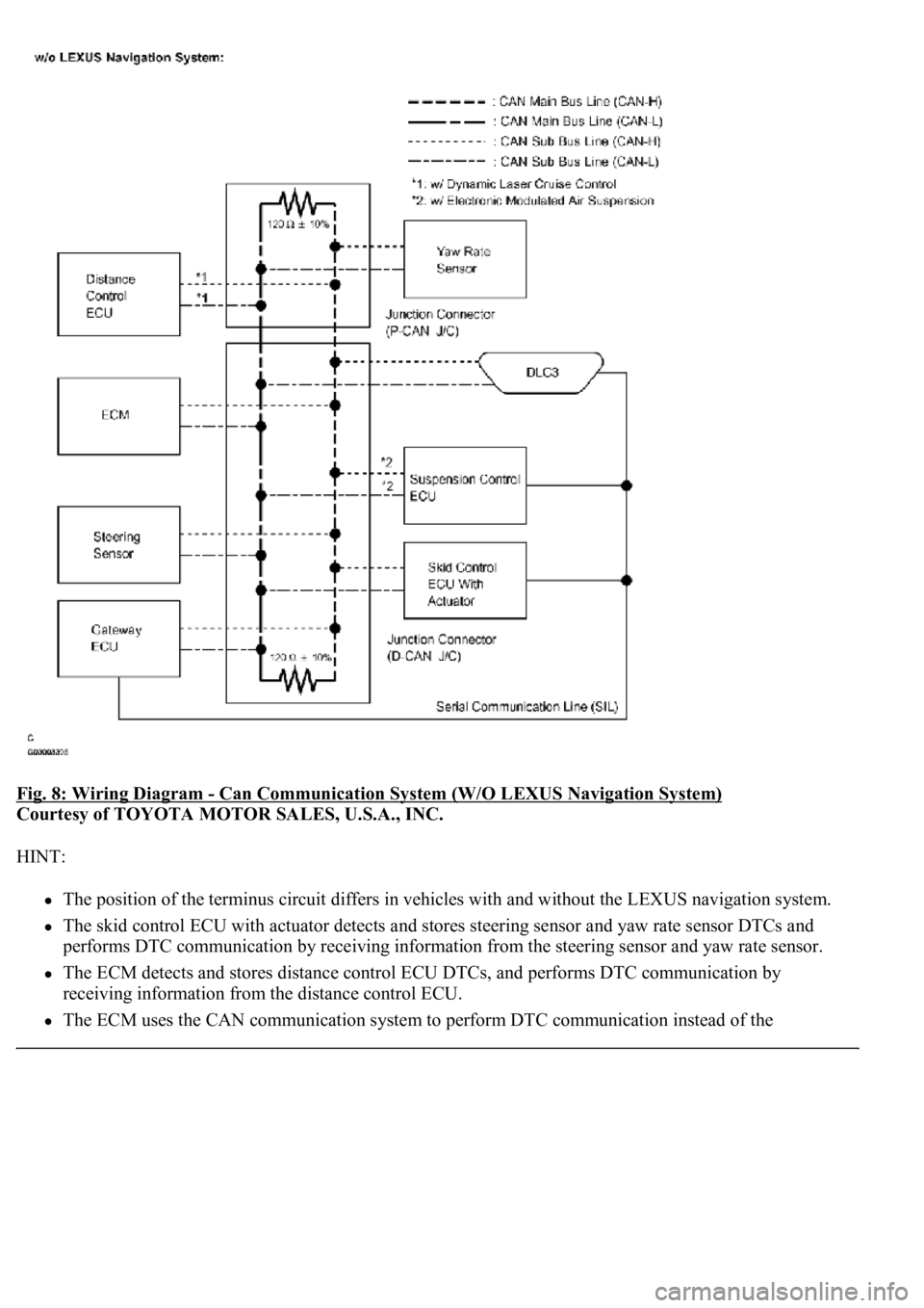
Fig. 8: Wiring Diagram - Can Communication System (W/O LEXUS Navigation System)
Courtesy of TOYOTA MOTOR SALES, U.S.A., INC.
HINT:
The position of the terminus circuit differs in vehicles with and without the LEXUS navigation system.
The skid control ECU with actuator detects and stores steering sensor and yaw rate sensor DTCs and
performs DTC communication by receiving information from the steering sensor and yaw rate sensor.
The ECM detects and stores distance control ECU DTCs, and performs DTC communication by
receiving information from the distance control ECU.
The ECM uses the CAN communication system to perform DTC communication instead of the
Page 1199 of 4500
conventional communication line (SIL).
1.BRIEF DESCRIPTION
a. The CAN (Controller Area Network) is a serial data communication system for real time
application. It is a multiplex communication system equipped for a vehicle and has a high
communication speed (500 kbps) and the function to detect malfunctions.
b. By pairing the CANH and CANL bus lines, the CAN performs communication based on
differential voltage.
c. Many ECUs (sensors) installed on the vehicle operate by sharing information and communicating
with each other.
d. The CAN has two resistors of 120 ohms which are necessary to communicate with the main bus
line.
2.DEFINITION OF TERMS
a. Main bus line
1. The main bus line is the wire harness between the two terminus circuits on the bus
(communication line). This is the main bus in the CAN communication system.
b. Sub bus line
1. The sub bus line is the wire harness which diverges from the main bus line to the ECU or
sensor.
c. Terminus circuit
1. The terminus circuit is a circuit which is placed to convert communication current of the
CAN communication into bus voltage. It consists of a resistor and condenser. Two terminus
circuits are necessary on a bus.
d. CAN J/C
1. The CAN J/C is a junction designed for CAN communication, which stores a terminus
circuit.
3.ECUs OR SENSORS WHICH COMMUNICATE THROUGH CAN COMMUNICATION
SYSTEM
a. Skid Control ECU with Actuator
b. Yaw Rate Sensor
c. Steering Sensor
d. Television Camera ECU
e. Seat Belt Control ECU
f. Distance Control ECU
g. Suspension Control ECU
h. ECM
i. Gateway ECU
4.DIAGNOSTIC CODE FOR CAN COMMUNICATION SYSTEM
a. DTCs for the CAN communication system are as follows: