Page 608 of 4500
Fig. 124: Steering Angle Sensor Wiring Diagram
Courtesy of TOYOTA MOTOR SALES, U.S.A., INC.
INSPECTION PROCEDURE
1.READ VALUE ON HAND-HELD TESTER
a. Connect the han
d-held tester to the DLC3.
Page 609 of 4500

b. Turn the ignition switch to the ON position and turn the hand-held tester main switch on.
c. Select the item below in the DATA LIST and read its value displayed on the hand-held tester.
AIR SUS:
Fig. 125: Data List Value Description
Courtesy of TOYOTA MOTOR SALES, U.S.A., INC.
d. Check that the steering wheel turning angle value of the steering angle position sensor displayed on
the hand-held tester changes when turning the steering wheel.
Standard:
Steering wheel turning angle value changes.
NG: Go to step 2
OK: REPLACE SUSPENSION CONTROL ECU (SEE REPLACEMENT
)
2.CHECK DIAGNOSTIC CODE OUTPUT
a. Check if the normal system code is output in the CAN communication system (SEE
SUSPENSION CONTROL ECU COMMUNICATION STOP MODE
).
OK:
No DTC is output in the CAN communication system.
NG: REPAIR CIRCUIT INDICATED BY OUTPUT CODE
OK:Go to next step
3.CHECK HARNESS AND CONNECTOR (STEERING SENSOR POWER SOURCE)
a. Disconnect the steering sensor S16 connector.
b. Turn the ignition switch to the ON position.
c. Measure the voltage according to the value (s) in the table below.
TESTER CONNECTION STANDARD SPECIFIED CONDITION
NG: REPAIR OR REPLACE HARNESS OR CONNECTOR
Tester ConnectionSpecified Condition
S16-1 (IG1) - S16-2 (ESS)10 to 14 V
S16-3 (BAT) - S16-2 (ESS)10 to 14 V
Page 610 of 4500
Fig. 126: Identifying Steering Sensor S16 Connector Terminals
Courtesy of TOYOTA MOTOR SALES, U.S.A., INC.
OK: REPLACE STEERING SENSOR (SEE REPLACEMENT
)
CIRCUIT DESCRIPTION
The height control switch turns on when it is pressed to the "HIGH" side and turns off when pressed to the
"NORM" side. The ECU detects the height control switch condition and raises or lowers the vehicle height
accordingly.
B
y controlling the height control switch, the vehicle height can be set 30 mm (1.18 in.) higher in "HIGH" mode.
Page 678 of 4500
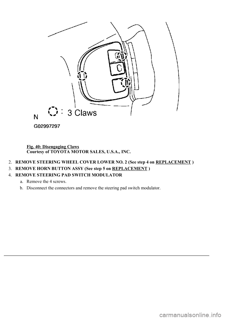
Fig. 40: Disengaging Claws
Courtesy of TOYOTA MOTOR SALES, U.S.A., INC.
2.REMOVE STEERING WHEEL COVER LOWER NO. 2 (See step 4 on REPLACEMENT
)
3.REMOVE HORN BUTTON ASSY (See step 5 on REPLACEMENT
)
4.REMOVE STEERING PAD SWITCH MODULATOR
a. Remove the 4 screws.
b. Disconnect the connectors and remove the steering pad switch modulator.
Page 704 of 4500
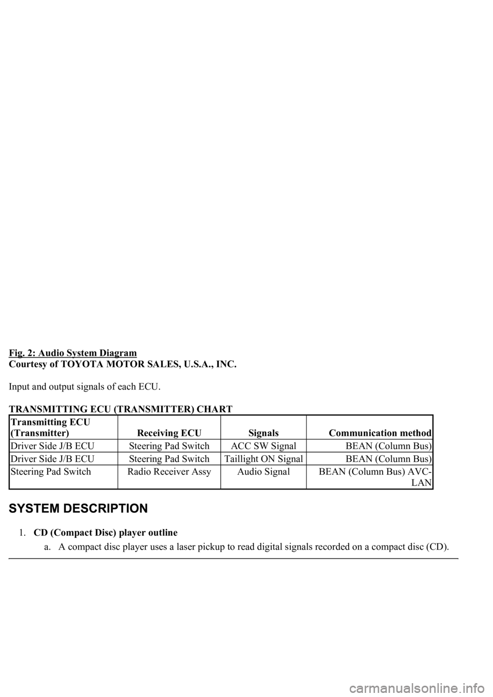
Fig. 2: Audio System Diagram
Courtesy of TOYOTA MOTOR SALES, U.S.A., INC.
Input and output signals of each ECU.
TRANSMITTING ECU (TRANSMITTER) CHART
1.CD (Compact Disc) player outline
a. A compact disc player uses a laser pickup to read digital signals recorded on a compact disc (CD).
Transmitting ECU
(Transmitter)
Receiving ECUSignalsCommunication method
Driver Side J/B ECUSteering Pad SwitchACC SW SignalBEAN (Column Bus)
Driver Side J/B ECUSteering Pad SwitchTaillight ON SignalBEAN (Column Bus)
Steering Pad SwitchRadio Receiver AssyAudio SignalBEAN (Column Bus) AVC-
LAN
Page 716 of 4500
Fig. 11: Identifying Rear Audio And Rear A/C Control SW Function Chart
Courtesy of TOYOTA MOTOR SALES, U.S.A., INC.
STEERING PAD FUNCTION
Fig. 12: Identifying Steering Pad Function Chart
Courtesy of TOYOTA MOTOR SALES, U.S.A., INC.
1.RADIO RECEIVER ASSY
Fig. 13: Radio Receiver Assy ECU Terminal Connector
Courtesy of TOYOTA MOTOR SALES, U.S.A., INC.
Page 801 of 4500
Fig. 83: Identifying Steering Pad Switch Item Condition Chart
Courtesy of TOYOTA MOTOR SALES, U.S.A., INC.
OK: PROCEED TO NEXT CIRCUIT INSPECTION SHOWN IN PROBLEM SYMPTOMS
TABLE
NG: REPLACE STEERING PAD SWITCH (SEE REPLACEMENT
)
CIRCUIT DESCRIPTION
Each unit of the radio receiver system connected to AVC-LAN (communication bus) communicates by
transferring the signals from each switch.
When +B short and GND short occur in this AVC-LAN, radio receiver system will not function normally as
communication is discontinued.
In AVC-LAN, radio receiver assy becomes the communication master, and the radio receiver assy has enough
resistance necessary for transmitting the communication.
WIRING DIAGRAM
Page 985 of 4500
23.INSTALL OUTER MIRROR SWITCH ASSY
24.INSTALL COIN BOX
25.INSTALL INSTRUMENT PANEL UNDER COVER NO.1 (SEE REPLACEMENT
)
26.INSTALL CLUSTER FINISH PANEL CENTER LOWER
27.INSTALL INSTRUMENT CLUSTER FINISH PANEL END
28.INSTALL SEAT ASSY FR LH
29.INSTALL SEAT TRACK BRACKET COVER INNER FRONT
30.INSTALL SEAT TRACK BRACKET COVER OUTER FRONT
31.INSTALL SEAT TRACK OUTER COVER LH
32.INSTALL SEAT TRACK COVER RH
33.INSTALL SEAT BELT ANCHOR COVER CAP LH
OVERHAUL
1.DISCONNECT BATTERY NEGATIVE TERMINAL
2.PLACE FRONT WHEELS FACING STRAIGHT AHEAD
3.REMOVE SWITCH & VOLUME CASE
4.REMOVE STEERING WHEEL COVER LOWER NO.2
5.REMOVE HORN BUTTON ASSY (SEE OVERHAUL
)
6.REMOVE STEERING WHEEL ASSY (SEE OVERHAUL
)
<00360036003700030013001c001c001800130010001800130013001400160003000b0013001c001c00180014001000130018001300140013000f00030013001c001c00180015001000130018001300140013000f00030013001c001c001800160010001300
18001300150013000f00030013001c001c0018001700100013[5021)
7.REMOVE STEERING COLUMN COVER (SEE OVERHAUL
)
8.REMOVE SPIRAL CABLE SUB-ASSY (SEE REPLACEMENT
)
9.REMOVE TURN SIGNAL SWITCH ASSY (SEE REPLACEMENT
)
10.REMOVE INSTRUMENT CLUSTER FINISH PANEL CENTER LOWER
11.REMOVE INSTRUMENT CLUSTER FINISH PANEL END
12.REMOVE INSTRUMENT PANEL UNDER COVER SUB-ASSY NO.1 (SEE REPLACEMENT
)
13.REMOVE COIN BOX ASSY
14.REMOVE OUTER MIRROR SWITCH ASSY
15.REMOVE INSTRUMENT PANEL SAFETY PAD SUB-ASSY NO.1 (SEE REPLACEMENT
)
16.REMOVE INSTRUMENT PANEL AIR BAG ASSY LOWER NO.1 (SEE REPLACEMENT
)
17.REMOVE INSTRUMENT PANEL UNDER COVER SUB-ASSY NO.2 (SEE REPLACEMENT
)
18.REMOVE INSTRUMENT CLUSTER FINISH PANEL (SEE REPLACEMENT
)
19.REMOVE COMBINATION METER ASSY (SEE OVERHAUL
)
20.REMOVE PUSH ROD PIN
a. Disconnect the stop lamp switch connector and brake pedal load sensing switch connector.