Page 120 of 4500
CONDITION DESCRIPTION
B: REPAIR OR REPLACE HARNESS OR CONNECTOR
Fig. 86: Oscilloscope Waveform Signal Description
Courtesy of TOYOTA MOTOR SALES, U.S.A., INC.
A: Go to next step
3.RECONFIRM DTC
a. Clear the DTC.
b. Turn the ignition switch to the ON position.
c. Check that the same DTC is recorded (see DTC CHECK/CLEAR
).
OK: Go to next step
The same DTC is recorded.
NG: REPLACE ABS & TRACTION ACTUATOR ASSY
OKNo ChangeA
NGChangeB
Page 135 of 4500
OK: Go to next step
5.RECONFIRM DTC
a. Clear the DTC (see DTC CHECK/CLEAR
).
b. Turn the ignition switch to the ON position.
c. Check that the same DTC is recorded (see DTC CHECK/CLEAR
).
OK:
The same DTC is recorded.
NG: PROCEED TO NEXT CIRCUIT INSPECTION SHOWN IN PROBLEM SYMPTOMS
TABLE
OK: REPLACE ABS & TRACTION ACTUATOR ASSY (SEE REPLACEMENT
)
6.INSPECT STOP LAMP SWITCH ASSY
a. Disconnect the stop lamp switch assy connector.
b. Measure the resistance according to the value (s) in the table below.
Standard:
TESTER CONNECTION SPECIFIED CONDITION
Switch ConditionTester ConnectionSpecified Condition
Switch pin free1 - 2Below 1 ohms
Switch pin pushed in1 - 21 Mohms or higher
Page 140 of 4500
OK: Go to next step
9.RECONFIRM DTC
a. Clear the DTC (see DTC CHECK/CLEAR
).
b. Turn the ignition switch to the ON position.
c. Check that the same DTC is recorded (see DTC CHECK/CLEAR
).
OK:
The same DTC is recorded.
NG: PROCEED TO NEXT CIRCUIT INSPECTION SHOWN IN PROBLEM SYMPTOMS
TABLE
OK: REPLACE ABS & TRACTION ACTUATOR ASSY (SEE REPLACEMENT
)
CIRCUIT DESCRIPTION
ABS pump motor is located inside the brake actuator. The motor is used for BA, TRAC and VSC operation.
Fig. 104: DTC C1251/51 Detection Condition And Trouble Area Description Chart
Courtesy of TOYOTA MOTOR SALES, U.S.A., INC.
WIRING DIAGRAM
Page 145 of 4500

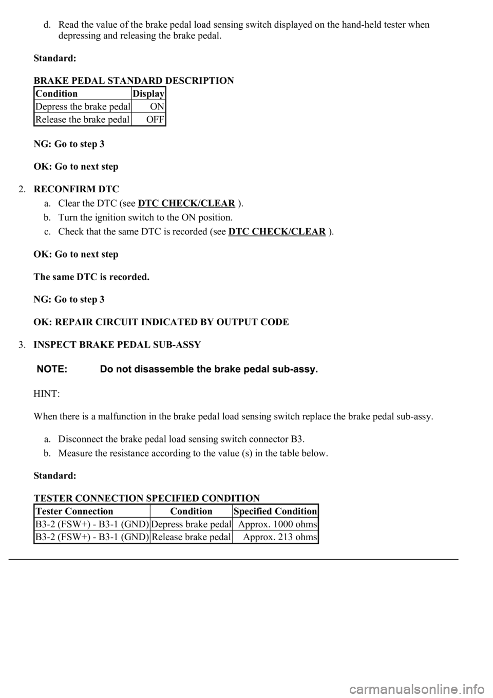
d. Read the value of the brake pedal load sensing switch displayed on the hand-held tester when
depressing and releasing the brake pedal.
Standard:
BRAKE PEDAL STANDARD DESCRIPTION
NG: Go to step 3
OK: Go to next step
2.RECONFIRM DTC
a. Clear the DTC (see DTC CHECK/CLEAR
).
b. Turn the ignition switch to the ON position.
c. Check that the same DTC is recorded (see DTC CHECK/CLEAR
).
OK: Go to next step
The same DTC is recorded.
NG: Go to step 3
OK: REPAIR CIRCUIT INDICATED BY OUTPUT CODE
3.INSPECT BRAKE PEDAL SUB-ASSY
HINT:
When there is a malfunction in the brake pedal load sensing switch replace the brake pedal sub-assy.
a. Disconnect the brake pedal load sensing switch connector B3.
b. Measure the resistance according to the value (s) in the table below.
Standard:
TESTER CONNECTION SPECIFIED CONDITION
ConditionDisplay
Depress the brake pedalON
Release the brake pedalOFF
Tester ConnectionConditionSpecified Condition
B3-2 (FSW+) - B3-1 (GND)Depress brake pedalApprox. 1000 ohms
B3-2 (FSW+) - B3-1 (GND)Release brake pedalApprox. 213 ohms
Page 190 of 4500
Fig. 134: TC And CG Terminal Wiring Diagram
Courtesy of TOYOTA MOTOR SALES, U.S.A., INC.
INSPECTION PROCEDURE
1.INSPECT DLC3 TERMINAL VOLTAGE (DLC3 TERMINAL VOLTAGE)
a. Turn the ignition switch to the ON position.
b. Measure the voltage according to the value (s) in the table below.
Standard:
TESTER CONNECTION SPECIFIED CONDITION
NG: GO TO STEP 3
Tester ConnectionSpecified Condition
D1-13 (TC) - Body ground10 to 14 V
Page 195 of 4500
Result:
DTC OUTPUT DESCRIPTION
B: REPAIR CIRCUIT INDICATED BY OUTPUT CODE (SEE DIAGNOSTIC TROUBLE CODE
CHART )
A: REPLACE ABS & TRACTION ACTUATOR ASSY (SEE REPLACEMENT
)
CIRCUIT DESCRIPTION
In the sensor check mode, a malfunction of the speed sensor that cannot be detected when the vehicle is stopped
is detected while driving.
Transition to the sensor check mode can be performed by connecting terminals TS and CG of the DLC3 and
turning the ignition switch from off to the ON position.
WIRING DIAGRAM
DTC is not outputA
DTC is outputB
Page 196 of 4500
Fig. 138: TS And CG Terminal Wiring Diagram
Courtesy of TOYOTA MOTOR SALES, U.S.A., INC.
INSPECTION PROCEDURE
1.INSPECT DLC3 TERMINAL VOLTAGE (TS TERMINAL)
a. Turn the ignition switch to the ON position.
b. Measure the voltage according to the value (s) in the table below.
Standard:
TESTER CONNECTION SPECIFIED CONDITION
NG: Go to step 3
Tester ConnectionSpecified Condition
D1-12 (TS) - D1-4 (CG)10 to 14 V
Page 217 of 4500

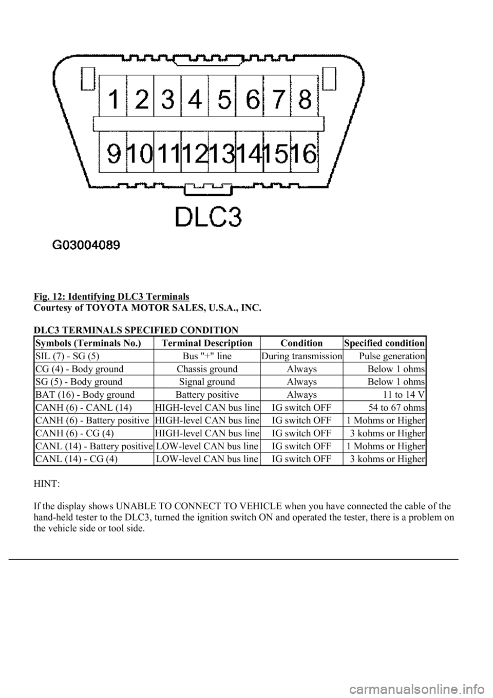
Fig. 12: Identifying DLC3 Terminals
Courtesy of TOYOTA MOTOR SALES, U.S.A., INC.
DLC3 TERMINALS SPECIFIED CONDITION
HINT:
If the display shows UNABLE TO CONNECT TO VEHICLE when you have connected the cable of the
hand-held tester to the DLC3, turned the ignition switch ON and operated the tester, there is a problem on
the vehicle side or tool side.
Symbols (Terminals No.)Terminal DescriptionConditionSpecified condition
SIL (7) - SG (5)Bus "+" lineDuring transmissionPulse generation
CG (4) - Body groundChassis groundAlwaysBelow 1 ohms
SG (5) - Body groundSignal groundAlwaysBelow 1 ohms
BAT (16) - Body groundBattery positiveAlways11 to 14 V
CANH (6) - CANL (14)HIGH-level CAN bus lineIG switch OFF54 to 67 ohms
CANH (6) - Battery positiveHIGH-level CAN bus lineIG switch OFF1 Mohms or Higher
CANH (6) - CG (4)HIGH-level CAN bus lineIG switch OFF3 kohms or Higher
CANL (14) - Battery positiveLOW-level CAN bus lineIG switch OFF1 Mohms or Higher
CANL (14) - CG (4)LOW-level CAN bus lineIG switch OFF3 kohms or Higher