Page 217 of 4500

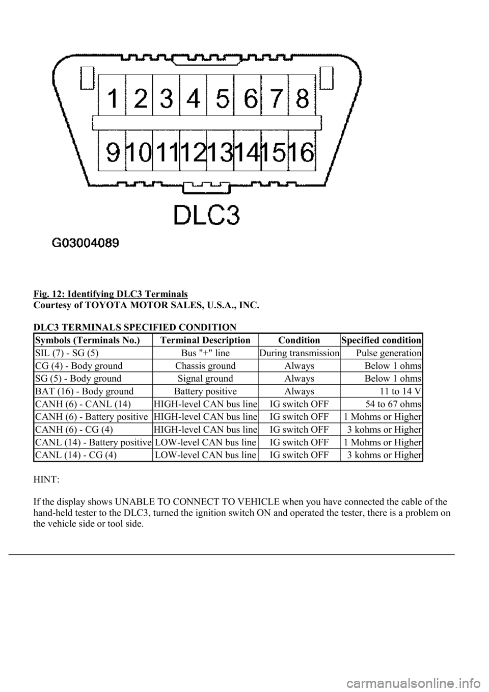
Fig. 12: Identifying DLC3 Terminals
Courtesy of TOYOTA MOTOR SALES, U.S.A., INC.
DLC3 TERMINALS SPECIFIED CONDITION
HINT:
If the display shows UNABLE TO CONNECT TO VEHICLE when you have connected the cable of the
hand-held tester to the DLC3, turned the ignition switch ON and operated the tester, there is a problem on
the vehicle side or tool side.
Symbols (Terminals No.)Terminal DescriptionConditionSpecified condition
SIL (7) - SG (5)Bus "+" lineDuring transmissionPulse generation
CG (4) - Body groundChassis groundAlwaysBelow 1 ohms
SG (5) - Body groundSignal groundAlwaysBelow 1 ohms
BAT (16) - Body groundBattery positiveAlways11 to 14 V
CANH (6) - CANL (14)HIGH-level CAN bus lineIG switch OFF54 to 67 ohms
CANH (6) - Battery positiveHIGH-level CAN bus lineIG switch OFF1 Mohms or Higher
CANH (6) - CG (4)HIGH-level CAN bus lineIG switch OFF3 kohms or Higher
CANL (14) - Battery positiveLOW-level CAN bus lineIG switch OFF1 Mohms or Higher
CANL (14) - CG (4)LOW-level CAN bus lineIG switch OFF3 kohms or Higher
Page 230 of 4500

Fig. 22: Identifying Air Conditioning Amplifier Connector Front View
Courtesy of TOYOTA MOTOR SALES, U.S.A., INC.
AIR CONDITIONING AMPLIFIER CONNECTOR SPECIFICATIONS
ItemTest Details / Display (Range)Diagnostic Note
ACTUATOR CHECKActuator check / OFF, ON-
Symbols
(Terminal No.)Wiring
colorTerminal DescriptionConditionSpecification
GND - Body
ground (A11-1 -
Body ground)W-B -
Body
groundGround for main power
supplyAlwaysBelow 1.0
ohms
MPX+ (A11-2)GR-BMultiplex communication
systemMultiplex communication circuit-
ACC - GND
(A11-3 - A11-1)GR - W-
BPower source (ACC)Turn ignition switch to ACC.10 to 14 V
MPX- (A11-4)GR-BMultiplex communication
systemMultiplex communication circuit-
BLW - GND
(A11-5 - A11-1)LG-B -
W-BBlower motor speed
control voltageBlower fan speed OFF --> M2 -->
HIPulse
generation
SOL+ - SOL-
(A11-6 - A11-7)P - Y-BCompressor operation
signalA/C magnetic clutch to ON.Pulse
generation
RDFGR - GND
(A11-8 - A11-1)W - W-BRear defogger operation
voltageIgnition switch ON. Rear
defogger switch to OFF.10 to 14 V
RDFGR - GND
(A11-8 - A11-1)W - W-BRear defogger operation
voltageIgnition switch ON. Rear
defogger switch to ON.Below 1.0 V
IG - GND (A11-9
- A11-1)LG-R -
W-BPower source (IG)Ignition switch ON.10 to 14 V
Page 237 of 4500

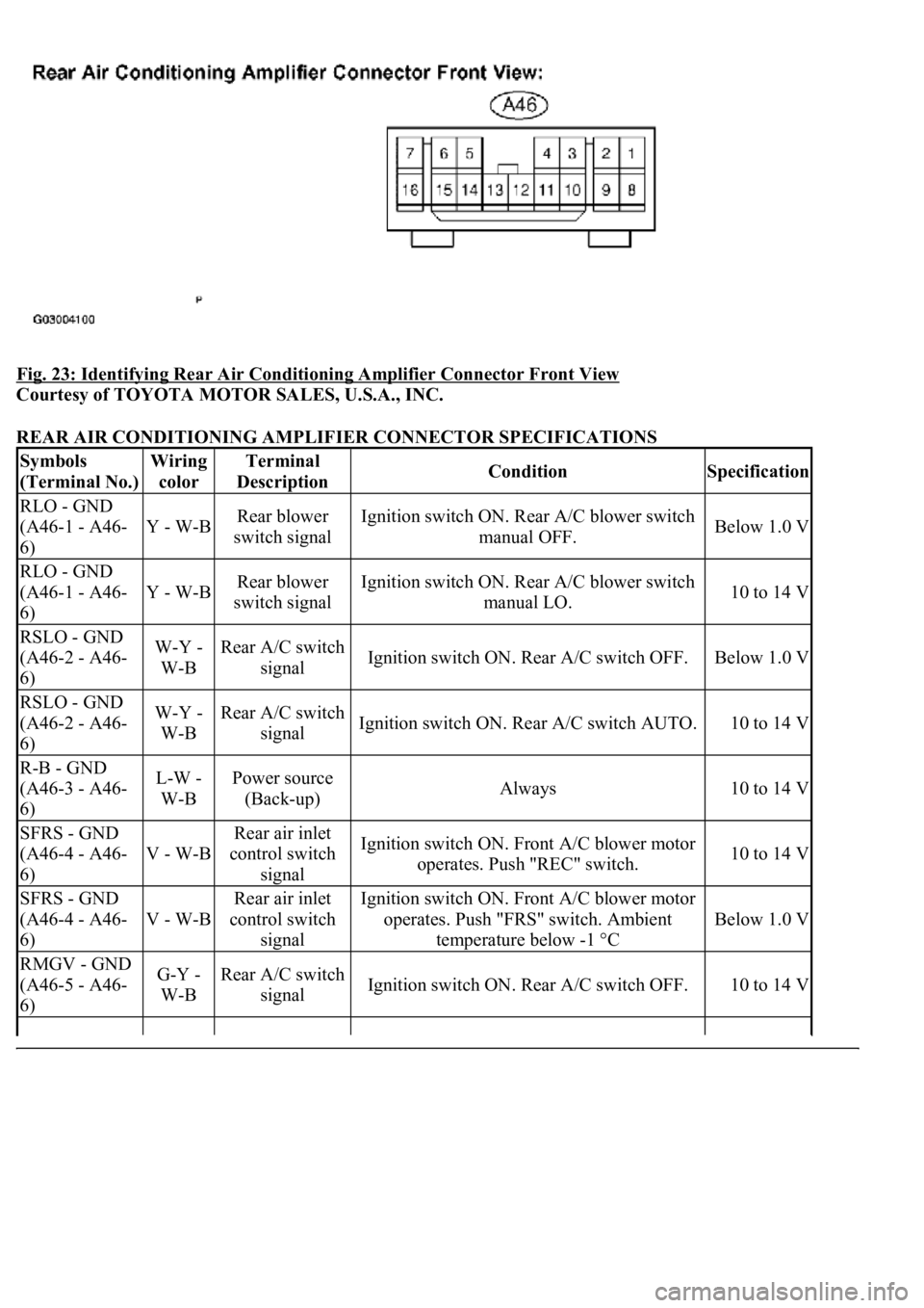
Fig. 23: Identifying Rear Air Conditioning Amplifier Connector Front View
Courtesy of TOYOTA MOTOR SALES, U.S.A., INC.
REAR AIR CONDITIONING AMPLIFIER CONNECTOR SPECIFICATIONS
Symbols
(Terminal No.)Wiring
colorTerminal
DescriptionConditionSpecification
RLO - GND
(A46-1 - A46-
6)
Y - W-BRear blower
switch signalIgnition switch ON. Rear A/C blower switch
manual OFF.Below 1.0 V
RLO - GND
(A46-1 - A46-
6)
Y - W-BRear blower
switch signalIgnition switch ON. Rear A/C blower switch
manual LO.10 to 14 V
RSLO - GND
(A46-2 - A46-
6)W-Y -
W-BRear A/C switch
signalIgnition switch ON. Rear A/C switch OFF.Below 1.0 V
RSLO - GND
(A46-2 - A46-
6)W-Y -
W-BRear A/C switch
signalIgnition switch ON. Rear A/C switch AUTO.10 to 14 V
R-B - GND
(A46-3 - A46-
6)L-W -
W-BPower source
(Back-up)Always10 to 14 V
SFRS - GND
(A46-4 - A46-
6)
V - W-B
Rear air inlet
control switch
signalIgnition switch ON. Front A/C blower motor
operates. Push "REC" switch.10 to 14 V
SFRS - GND
(A46-4 - A46-
6)
V - W-B
Rear air inlet
control switch
signalIgnition switch ON. Front A/C blower motor
operates. Push "FRS" switch. Ambient
temperature below -1 °C
Below 1.0 V
RMGV - GND
(A46-5 - A46-
6)G-Y -
W-BRear A/C switch
signalIgnition switch ON. Rear A/C switch OFF.10 to 14 V
Page 239 of 4500

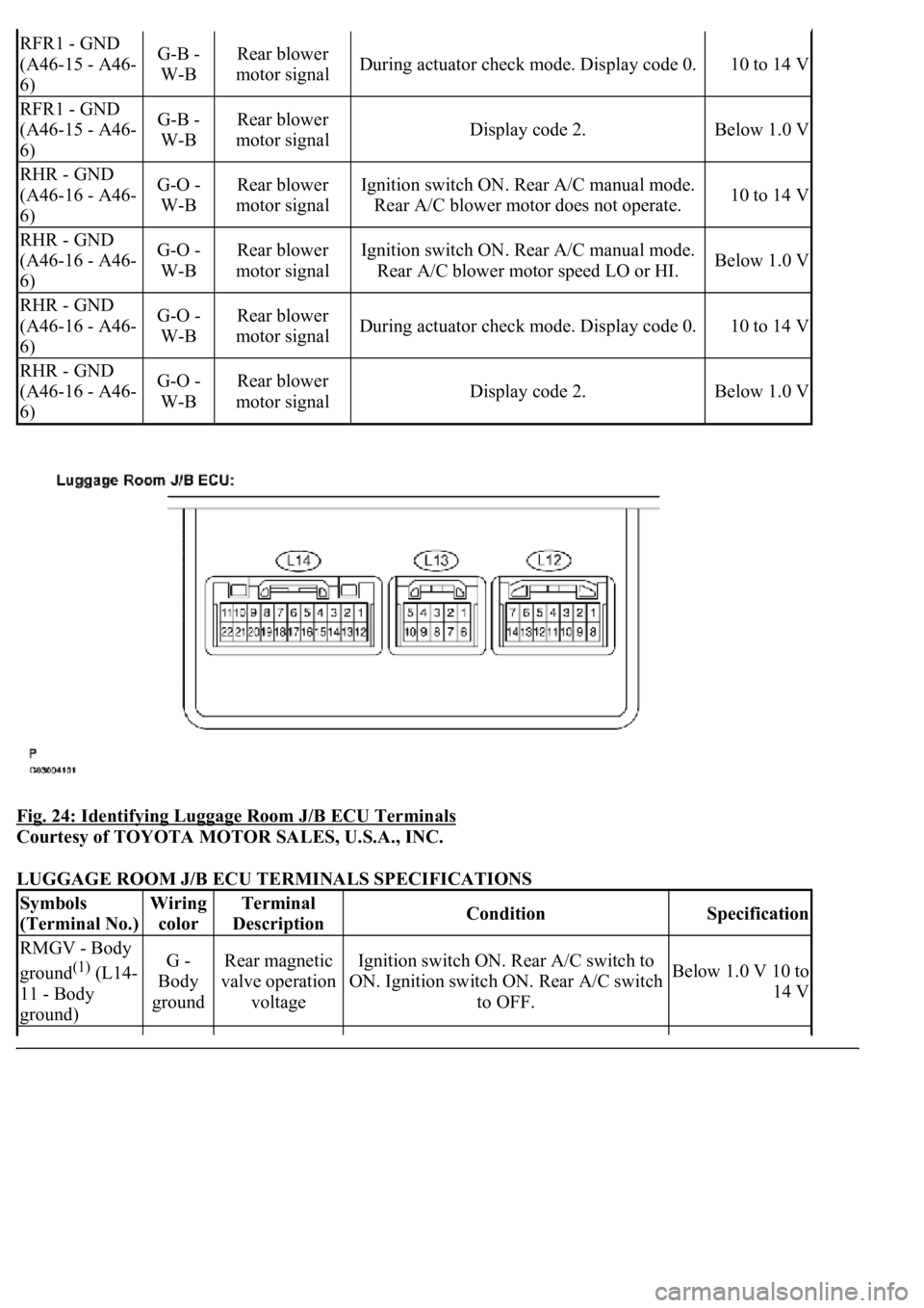
Fig. 24: Identifying Luggage Room J/B ECU Terminals
Courtesy of TOYOTA MOTOR SALES, U.S.A., INC.
LUGGAGE ROOM J/B ECU TERMINALS SPECIFICATIONS
RFR1 - GND
(A46-15 - A46-
6)G-B -
W-BRear blower
motor signalDuring actuator check mode. Display code 0.10 to 14 V
RFR1 - GND
(A46-15 - A46-
6)G-B -
W-BRear blower
motor signalDisplay code 2.Below 1.0 V
RHR - GND
(A46-16 - A46-
6)G-O -
W-BRear blower
motor signalIgnition switch ON. Rear A/C manual mode.
Rear A/C blower motor does not operate.10 to 14 V
RHR - GND
(A46-16 - A46-
6)G-O -
W-BRear blower
motor signalIgnition switch ON. Rear A/C manual mode.
Rear A/C blower motor speed LO or HI.Below 1.0 V
RHR - GND
(A46-16 - A46-
6)G-O -
W-BRear blower
motor signalDuring actuator check mode. Display code 0.10 to 14 V
RHR - GND
(A46-16 - A46-
6)G-O -
W-BRear blower
motor signalDisplay code 2.Below 1.0 V
Symbols
(Terminal No.)Wiring
colorTerminal
DescriptionConditionSpecification
RMGV - Body
ground
(1) (L14-
11 - Body
ground)G -
Body
groundRear magnetic
valve operation
voltageIgnition switch ON. Rear A/C switch to
ON. Ignition switch ON. Rear A/C switch
to OFF.Below 1.0 V 10 to
14 V
Page 271 of 4500
Fig. 53: Identifying Terminals Of A/C Evaporator Temperature Sensor Connector
Courtesy of TOYOTA MOTOR SALES, U.S.A., INC.
NG: REPAIR OR REPLACE HARNESS OR CONNECTOR
OK: REPLACE AIR CONDITIONING AMPLIFIER (SEE REPLACEMENT
)
CIRCUIT DESCRIPTION
This sensor detects the register temperature and sends the appropriate signals to the A/C amplifier.
Fig. 54: DTC Detection Item Trouble Area Chart
Courtesy of TOYOTA MOTOR SALES, U.S.A., INC.
Page 401 of 4500
Fig. 147: Identifying Location Of Fuse (A/C)
Courtesy of TOYOTA MOTOR SALES, U.S.A., INC.
OK: Go to next step
3.INSPECT AIR CONDITIONING AMPLIFIER (B - BODY GROUND)
a. Remove the A/C amplifier assy and disconnect the connector.
b. Measure the voltage according to the value (s) in the table below.
Standard:
AIR CONDITIONING AMPLIFIER (B - BODY GROUND) VOLTAGE
NG: REPAIR OR REPLACE WIRE HARNESS (AIR CONDITIONING AMPLIFIER -
BATTERY)
Tester connectionConditionSpecified condition
A11-21 (+B) - Body groundAlways10 to 14 V
Page 410 of 4500
Fig. 155: Identifying Location Of Fuse (P-ACC)
Courtesy of TOYOTA MOTOR SALES, U.S.A., INC.
OK: REPAIR OR REPLACE HARNESS OR CONNECTOR (AIR CONDITIONING
AMPLIFIER - BATTERY)
CIRCUIT DESCRIPTION
The blower motor is operated by signals from the A/C amplifier assy. Blower motor speed signals are
transmitted by changes in the duty ratio.
Duty Ratio
The duty ratio is the ratio of the period of continuity in one cycle. For example, if A is the period of continuity
in one cycle, B is the period of non-continuity.
The blower motor controller controls the blower motor speed.
Page 415 of 4500
Fig. 158: Identifying Location Of Fuse (Heater)
Courtesy of TOYOTA MOTOR SALES, U.S.A., INC.
OK: Go to next step
5.CHECK HARNESS AND CONNECTOR (BLOWER MOTOR - AIR CONDITIONING
AMPLIFIER) (SEE ELECTRONIC CIRCUIT INSPECTION PROCEDURE
)
a. Measure the resistance according to the value (s) in the table below.
Standard:
BLOWER MOTOR - AIR CONDITIONING AMPLIFIER RESISTANCE
Tester connectionConditionSpecified condition
A11-5 (BLW) -B2-2 (SI)AlwaysBelow 1 ohms
A11-5 (BLW) - Body groundAlways10 kohms or higher