Page 3001 of 4500
Fig. 17: Disconnecting Cable Clamps
Courtesy of TOYOTA MOTOR SALES, U.S.A., INC.
b. Pull the cable from the engine room and remove it.
Page 3002 of 4500
Fig. 18: Pulling Cable From Engine Room
Courtesy of TOYOTA MOTOR SALES, U.S.A., INC.
12.INSTALL HOOD LOCK CONTROL CABLE ASSY
a. Pass the cable to the engine room.
b. Pass the cable rear side through the grommet until the cable stopper is attached to the grommet.
c. Pass the cable front side throu
gh the upper radiator support.
Page 3165 of 4500
Fig. 1: Identifying Components & Replacements Location of Engine Immobilizer System (W/Smart Key
System)
Courtesy of TOYOTA MOTOR SALES, U.S.A., INC.
Page 3166 of 4500

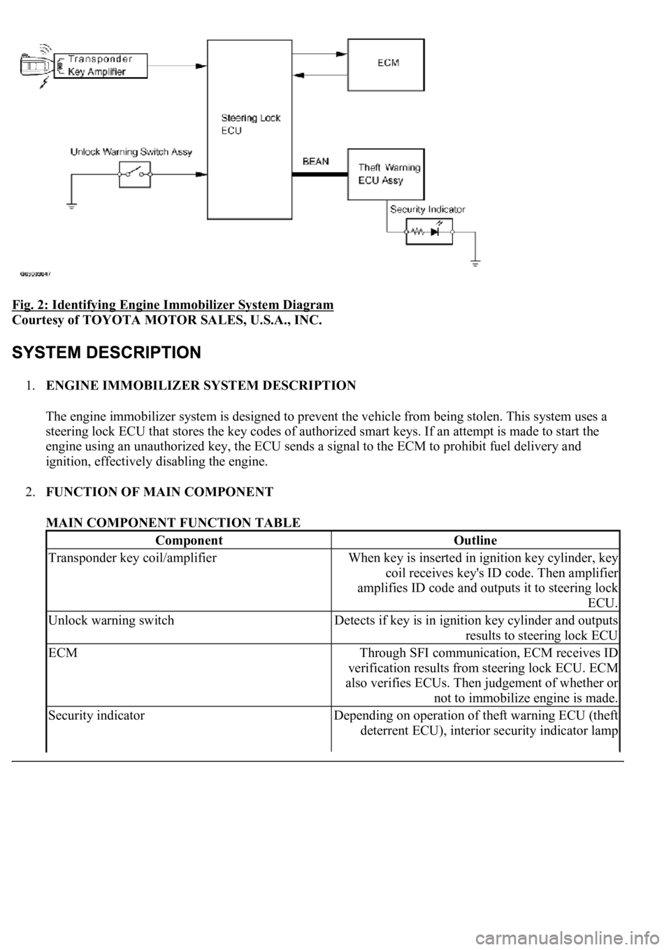
Fig. 2: Identifying Engine Immobilizer System Diagram
Courtesy of TOYOTA MOTOR SALES, U.S.A., INC.
1.ENGINE IMMOBILIZER SYSTEM DESCRIPTION
The engine immobilizer system is designed to prevent the vehicle from being stolen. This system uses a
steering lock ECU that stores the key codes of authorized smart keys. If an attempt is made to start the
engine using an unauthorized key, the ECU sends a signal to the ECM to prohibit fuel delivery and
ignition, effectively disabling the engine.
2.FUNCTION OF MAIN COMPONENT
MAIN COMPONENT FUNCTION TABLE
ComponentOutline
Transponder key coil/amplifierWhen key is inserted in ignition key cylinder, key
coil receives key's ID code. Then amplifier
amplifies ID code and outputs it to steering lock
ECU.
Unlock warning switchDetects if key is in ignition key cylinder and outputs
results to steering lock ECU
ECMThrough SFI communication, ECM receives ID
verification results from steering lock ECU. ECM
also verifies ECUs. Then judgement of whether or
not to immobilize engine is made.
Security indicatorDepending on operation of theft warning ECU (theft
deterrent ECU), interior security indicator lamp
Page 3167 of 4500

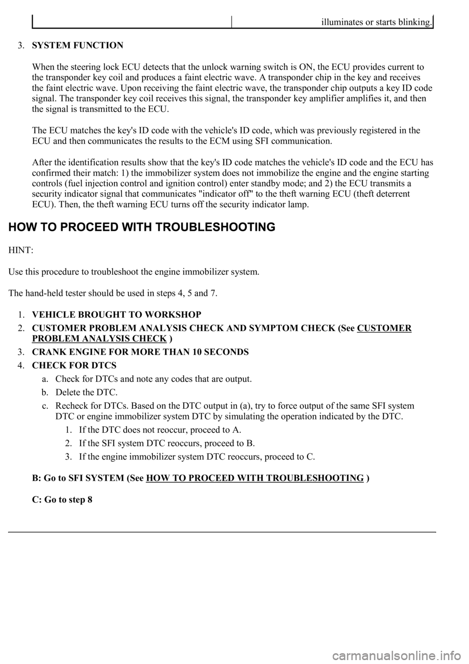
3.SYSTEM FUNCTION
When the steering lock ECU detects that the unlock warning switch is ON, the ECU provides current to
the transponder key coil and produces a faint electric wave. A transponder chip in the key and receives
the faint electric wave. Upon receiving the faint electric wave, the transponder chip outputs a key ID code
signal. The transponder key coil receives this signal, the transponder key amplifier amplifies it, and then
the signal is transmitted to the ECU.
The ECU matches the key's ID code with the vehicle's ID code, which was previously registered in the
ECU and then communicates the results to the ECM using SFI communication.
After the identification results show that the key's ID code matches the vehicle's ID code and the ECU has
confirmed their match: 1) the immobilizer system does not immobilize the engine and the engine starting
controls (fuel injection control and ignition control) enter standby mode; and 2) the ECU transmits a
security indicator signal that communicates "indicator off" to the theft warning ECU (theft deterrent
ECU). Then, the theft warning ECU turns off the security indicator lamp.
HINT:
Use this procedure to troubleshoot the engine immobilizer system.
The hand-held tester should be used in steps 4, 5 and 7.
1.VEHICLE BROUGHT TO WORKSHOP
2.CUSTOMER PROBLEM ANALYSIS CHECK AND SYMPTOM CHECK (See CUSTOMER
PROBLEM ANALYSIS CHECK )
3.CRANK ENGINE FOR MORE THAN 10 SECONDS
4.CHECK FOR DTCS
a. Check for DTCs and note any codes that are output.
b. Delete the DTC.
c. Recheck for DTCs. Based on the DTC output in (a), try to force output of the same SFI system
DTC or engine immobilizer system DTC by simulating the operation indicated by the DTC.
1. If the DTC does not reoccur, proceed to A.
2. If the SFI system DTC reoccurs, proceed to B.
3. If the engine immobilizer system DTC reoccurs, proceed to C.
B: Go to SFI SYSTEM (See HOW TO PROCEED WITH TROUBLESHOOTING
)
C: Go to step 8
illuminates or starts blinking.
Page 3179 of 4500
a. Register the ECU communication ID.
1. Using SST, connect terminals TC and CG of the DLC3.
SST 09843-18040
Fig. 9: Connecting Terminals TC And CG Of DLC3 Using SST
Courtesy of TOYOTA MOTOR SALES, U.S.A., INC.
2. Turn the ignition switch ON (do not start the engine) and leave it as is for 30 minutes.
3. Turn the ignition switch OFF and disconnect terminals TC and CG.
4. Check that the engine starts.
Fig. 10: Problem Symptoms Table
Courtesy of TOYOTA MOTOR SALES, U.S.A., INC.
1.CHECK TRANSPONDER KEY AMPLIFIER
Page 3200 of 4500
1.STEERING LOCK ECU DTC CHART
Fig. 27: Steering Lock ECU DTC Chart
Courtesy of TOYOTA MOTOR SALES, U.S.A., INC.
2.ECM DTC CHART
Fig. 28: ECM DTC Chart
Courtesy of TOYOTA MOTOR SALES, U.S.A., INC.
DTC B2793TRANSPONDER CHIP MALFUNCTION
DTC B2794UNMATCHED ENCRYPTION CODE
DTC B2795UNMATCHED KEY CODE
DTC B2797COMMUNICATION MALFUNCTION NO.1
DTC B2799ENGINE IMMOBILIZER SYSTEM
MALFUNCTION
Page 3201 of 4500
CIRCUIT DESCRIPTION
This DTC will be output if the steering lock ECU does not detect that the unlock warning switch is ON even
when the ignition switch is ON. Under the normal conditions, the unlock warning switch is ON when the
ignition switch is ON.
Fig. 29: Push Switch/Key Unlock Warning Switch Malfunction Circuit Description
Courtesy of TOYOTA MOTOR SALES, U.S.A., INC.
WIRING DIAGRAM
Fig. 30: Push Switch/Key Unlock Warning Switch Malfunction
- Wiring Diagram
Courtesy of TOYOTA MOTOR SALES, U.S.A., INC.
INSPECTION PROCEDURE
1.READ DATA LIST USING HAND-HELD TESTER
a. Connect the hand-held tester to the CAN VIM. Then connect the CAN VIM to the DLC3.
b. Turn the ignition switch ON with the key that cannot start the engine.
c. Read the DATA LIST.
Steering lock ECU:
DATA LIST - STEERING LOCK ECU
Measurement Item/