Page 2218 of 4500
NG: REPAIR OR REPLACE HARNESS AND CONNECTOR
OK: PROCEED TO NEXT CIRCUIT INSPECTION SHOWN ON PROBLEM SYMPTOMS
TABLE
CIRCUIT DESCRIPTION
This circuit supplies power to operate the rear door LH ECU.
WIRING DIAGRAM
Page 2219 of 4500
Fig. 48: Rear Door LH ECU Power Source Circuit - Wiring Diagram
Courtesy of TOYOTA MOTOR SALES, U.S.A., INC.
INSPECTION PROCEDURE
1.INSPECT FUSE (MPX-IG, AM1, RR DOOR LH, MPX-B1, D/C CUT)
a. Remove the MPX-IG and AM1 fuses from the driver side J/B.
Page 2222 of 4500
CIRCUIT DESCRIPTION
This circuit supplies power to operate the rear door RH ECU.
WIRING DIAGRAM
Page 2223 of 4500
Fig. 51: Rear Door RH ECU Power Source Circuit -Wiring Diagram
Courtesy of TOYOTA MOTOR SALES, U.S.A., INC.
INSPECTION PROCEDURE
1.INSPECT FUSE (MPX-IG, AM1, RR DOOR RH, MPX-B1, D/C CUT)
a. Remove the MPX-IG and AM1 fuses from the driver side J/B.
b. Remove the MPX-B1 and RR DOOR RH fuses from the passenger side J/B.
c. Remove the D/C CUT fuse from the FL block assy.
d. Measure the resistance.
Standard: Below 1 ohms
NG: REPLACE FUSE
OK: Go to Next Step.
2.INSPECT RELAY (Marking: D-IG1)
a. Remove the D-IG1 relay from the driver side J/B.
b. Measure the resistance.
Fig. 52: Inspecting Relay (D
-IG1)
Courtesy of TOYOTA MOTOR SALES, U.S.A., INC.
Page 2225 of 4500
NG: REPAIR OR REPLACE HARNESS AND CONNECTOR
OK: PROCEED TO NEXT CIRCUIT INSPECTION SHOWN ON PROBLEM SYMPTOMS
TABLE
CIRCUIT DESCRIPTION
The door lock assembly has a built-in closer position switch, which detects the position of the closer.
WIRING DIAGRAM
Fig. 54: Door Closer Position Switch Circuit On Driver Side Door
- Wiring Diagram
Courtesy of TOYOTA MOTOR SALES, U.S.A., INC.
INSPECTION PROCEDURE
1.READ VALUE OF DATA LIST (DOOR CLOSER POSITION SWITCH (POLE/HALF/ FULL))
a. Check the DATA LIST for proper functioning of the door closer position switch.
DRIVER DOOR EC
R14-1 (CPUB) - Body groundAlways10 to 14 V
R14-2 (BDR) - Body groundAlways10 to 14 V
R14-26 (SIG) Body groundIgnition switch ON10 to 14 V
Measurement item / Display
Page 2232 of 4500
Fig. 57: Checking Wire Harness (Driver Door ECU -Front Door Lock Assy LH)
Courtesy of TOYOTA MOTOR SALES, U.S.A., INC.
TERMINALS RESISTANCE REFERENCE
NG: REPLACE COMBINATION SWITCH ASSY
OK: PROCEED TO NEXT CIRCUIT INSPECTION SHOWN ON PROBLEM SYMPTOMS
TABLE
CIRCUIT DESCRIPTION
The door lock assembly has a built-in closer position switch, which detects the position of the closer.
WIRING DIAGRAM
Tester ConnectionSpecified Condition
F23-a-2 - F23-23 (POLE)Below 1 ohms
F23-a-1 - F23-24 (HALF)Below 1 ohms
F23-a-4 - F23-15 (FULL)Below 1 ohms
F23-a-5 - F23-21 (KEYE)Below 1 ohms
F23-a-2 - Body ground10 kohms or higher
F23-a-1 - Body ground10 kohms or higher
F23-a-4 - Body ground10 kohms or higher
F23-a-5 - Body ground10 kohms or higher
Page 2233 of 4500

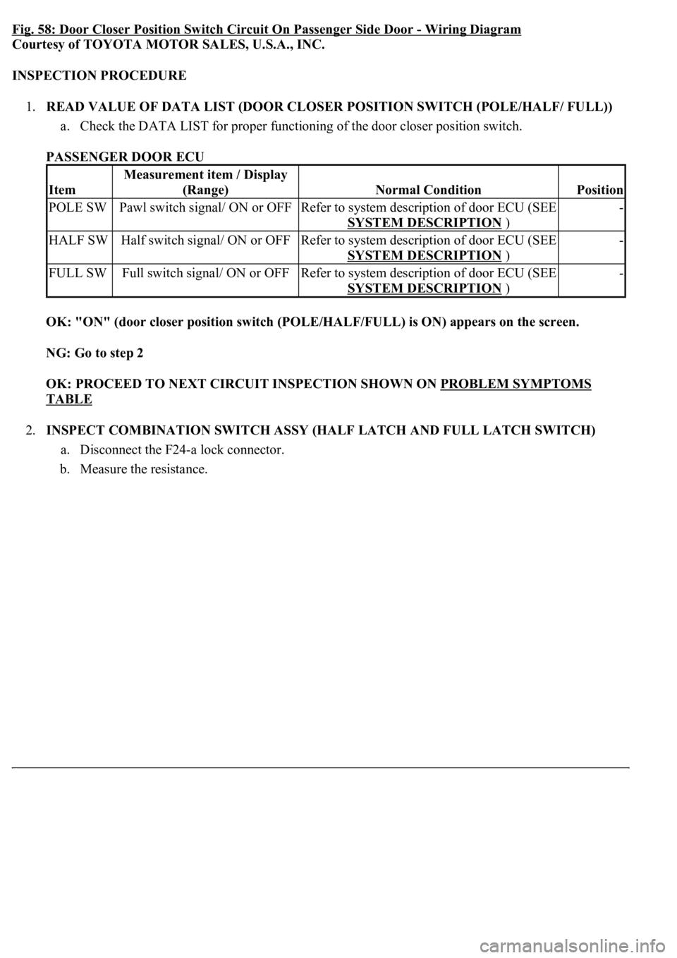
Fig. 58: Door Closer Position Switch Circuit On Passenger Side Door -Wiring Diagram
Courtesy of TOYOTA MOTOR SALES, U.S.A., INC.
INSPECTION PROCEDURE
1.READ VALUE OF DATA LIST (DOOR CLOSER POSITION SWITCH (POLE/HALF/ FULL))
a. Check the DATA LIST for proper functioning of the door closer position switch.
PASSENGER DOOR ECU
OK: "ON" (door closer position switch (POLE/HALF/FULL) is ON) appears on the screen.
NG: Go to step 2
OK: PROCEED TO NEXT CIRCUIT INSPECTION SHOWN ON PROBLEM SYMPTOMS
TABLE
2.INSPECT COMBINATION SWITCH ASSY (HALF LATCH AND FULL LATCH SWITCH)
a. Disconnect the F24-a lock connector.
b. Measure the resistance.
Item
Measurement item / Display
(Range)
Normal ConditionPosition
POLE SWPawl switch signal/ ON or OFFRefer to system description of door ECU (SEE
SYSTEM DESCRIPTION
)
-
HALF SWHalf switch signal/ ON or OFFRefer to system description of door ECU (SEE
SYSTEM DESCRIPTION
)
-
FULL SWFull switch signal/ ON or OFFRefer to system description of door ECU (SEE
SYSTEM DESCRIPTION
)
-
Page 2239 of 4500
Fig. 61: Checking Wire Harness (Passenger Door ECU -Front Door Lock Assy RH)
Courtesy of TOYOTA MOTOR SALES, U.S.A., INC.
NG: REPLACE COMBINATION SWITCH ASSY
OK: PROCEED TO NEXT CIRCUIT INSPECTION SHOWN ON PROBLEM SYMPTOMS
TABLE
CIRCUIT DESCRIPTION
The door lock assembly has a built-in closer position switch, which detects the position of the closer.
WIRING DIAGRAM
Fig. 62: Door Closer Position Switch Circuit On Rear Left Side Door
- Wiring Diagram
Courtesy of TOYOTA MOTOR SALES, U.S.A., INC.
INSPECTION PROCEDURE
1.READ VALUE OF DATA LIST (DOOR CLOSER POSITION SWITCH (POLE/HALF/ FULL))
a. Check the DATA LIST for proper functioning of the door closer position switch.
REAR DOOR LH ECU
Item
Measurement item / Display
(Range)
Normal ConditionPosition
POLE SWPawl switch signal/ ON or OFFRefer to system description of door ECU -