Page 912 of 4500
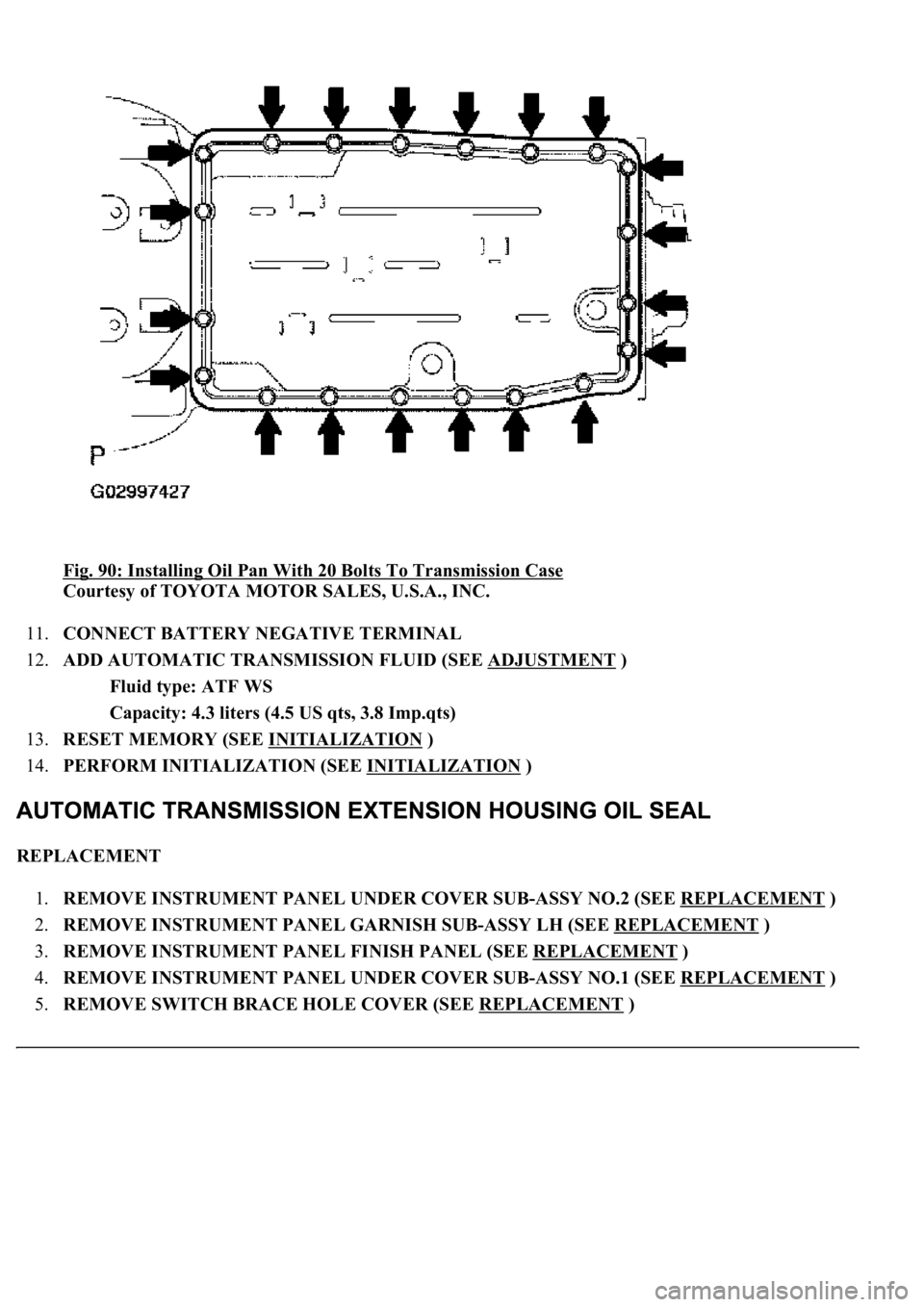
Fig. 90: Installing Oil Pan With 20 Bolts To Transmission Case
Courtesy of TOYOTA MOTOR SALES, U.S.A., INC.
11.CONNECT BATTERY NEGATIVE TERMINAL
12.ADD AUTOMATIC TRANSMISSION FLUID (SEE ADJUSTMENT
)
Fluid type: ATF WS
Capacity: 4.3 liters (4.5 US qts, 3.8 Imp.qts)
13.RESET MEMORY (SEE INITIALIZATION
)
14.PERFORM INITIALIZATION (SEE INITIALIZATION
)
REPLACEMENT
1.REMOVE INSTRUMENT PANEL UNDER COVER SUB-ASSY NO.2 (SEE REPLACEMENT
)
2.REMOVE INSTRUMENT PANEL GARNISH SUB-ASSY LH (SEE REPLACEMENT
)
3.REMOVE INSTRUMENT PANEL FINISH PANEL (SEE REPLACEMENT
)
4.REMOVE INSTRUMENT PANEL UNDER COVER SUB-ASSY NO.1 (SEE REPLACEMENT
)
5.REMOVE SWITCH BRACE HOLE COVER (SEE REPLACEMENT
)
Page 916 of 4500
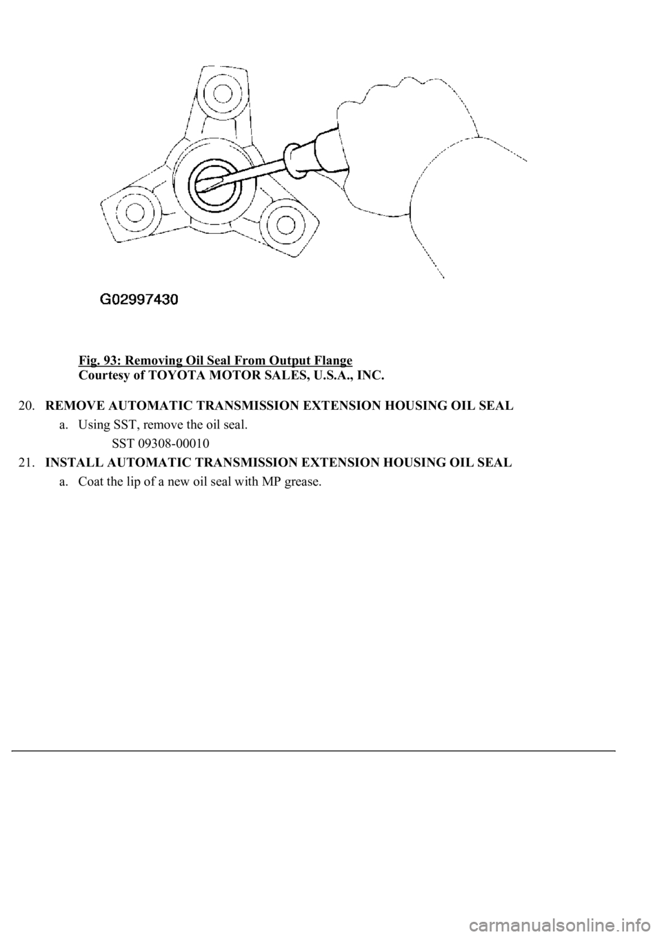
Fig. 93: Removing Oil Seal From Output Flange
Courtesy of TOYOTA MOTOR SALES, U.S.A., INC.
20.REMOVE AUTOMATIC TRANSMISSION EXTENSION HOUSING OIL SEAL
a. Using SST, remove the oil seal.
SST 09308-00010
21.INSTALL AUTOMATIC TRANSMISSION EXTENSION HOUSING OIL SEAL
a. Coat the lip of a new oil seal with MP
grease.
Page 918 of 4500
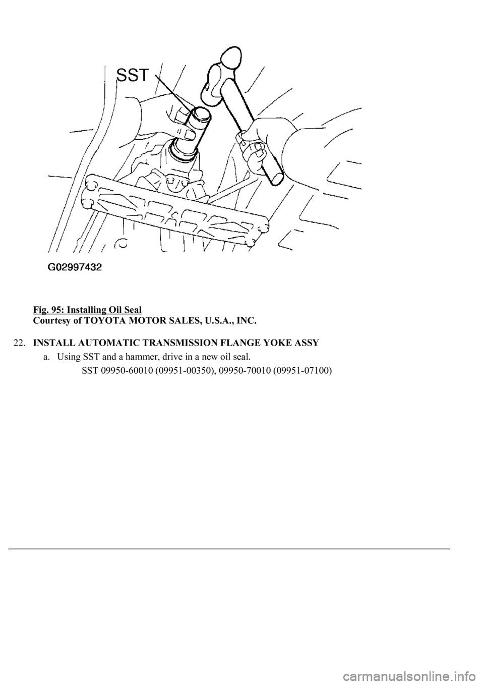
Fig. 95: Installing Oil Seal
Courtesy of TOYOTA MOTOR SALES, U.S.A., INC.
22.INSTALL AUTOMATIC TRANSMISSION FLANGE YOKE ASSY
a. Using SST and a hammer, drive in a new oil seal.
<00360036003700030013001c001c001800130010001900130013001400130003000b0013001c001c00180014001000130013001600180013000c000f00030013001c001c001800130010001a00130013001400130003000b0013001c001c00180014001000
13001a001400130013000c00030003[
Page 2634 of 4500
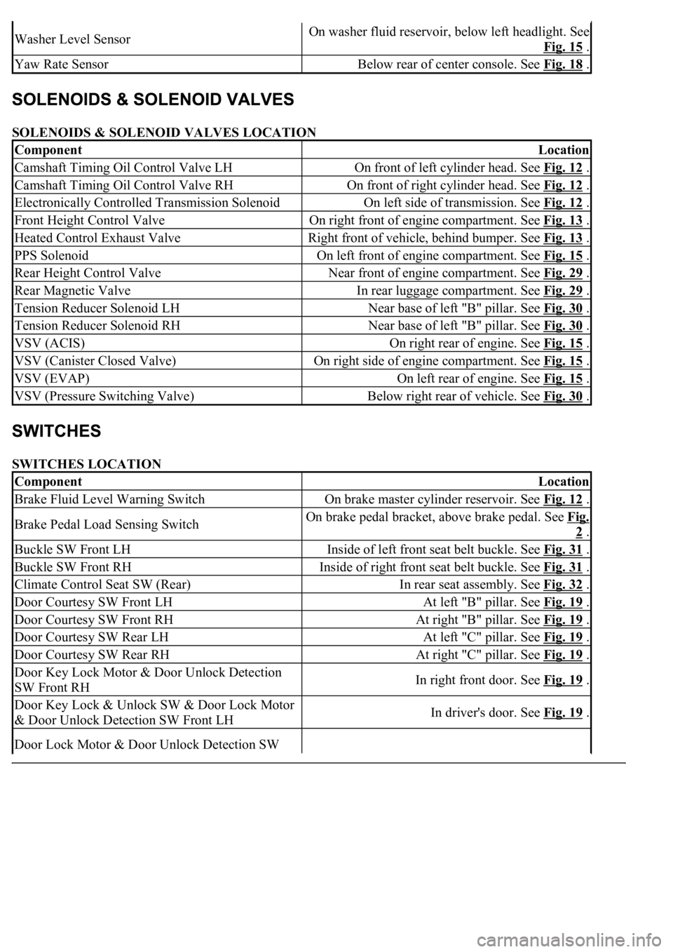
SOLENOIDS & SOLENOID VALVES LOCATION
SWITCHES LOCATION
Washer Level SensorOn washer fluid reservoir, below left headlight. See
Fig. 15
.
Yaw Rate SensorBelow rear of center console. See Fig. 18 .
ComponentLocation
Camshaft Timing Oil Control Valve LHOn front of left cylinder head. See Fig. 12 .
Camshaft Timing Oil Control Valve RHOn front of right cylinder head. See Fig. 12 .
Electronically Controlled Transmission SolenoidOn left side of transmission. See Fig. 12 .
Front Height Control ValveOn right front of engine compartment. See Fig. 13 .
Heated Control Exhaust ValveRight front of vehicle, behind bumper. See Fig. 13 .
PPS SolenoidOn left front of engine compartment. See Fig. 15 .
Rear Height Control ValveNear front of engine compartment. See Fig. 29 .
Rear Magnetic ValveIn rear luggage compartment. See Fig. 29 .
Tension Reducer Solenoid LHNear base of left "B" pillar. See Fig. 30 .
Tension Reducer Solenoid RHNear base of left "B" pillar. See Fig. 30 .
VSV (ACIS)On right rear of engine. See Fig. 15 .
VSV (Canister Closed Valve)On right side of engine compartment. See Fig. 15 .
VSV (EVAP)On left rear of engine. See Fig. 15 .
VSV (Pressure Switching Valve)Below right rear of vehicle. See Fig. 30 .
ComponentLocation
Brake Fluid Level Warning SwitchOn brake master cylinder reservoir. See Fig. 12 .
Brake Pedal Load Sensing SwitchOn brake pedal bracket, above brake pedal. See Fig.
2 .
Buckle SW Front LHInside of left front seat belt buckle. See Fig. 31 .
Buckle SW Front RHInside of right front seat belt buckle. See Fig. 31 .
Climate Control Seat SW (Rear)In rear seat assembly. See Fig. 32 .
Door Courtesy SW Front LHAt left "B" pillar. See Fig. 19 .
Door Courtesy SW Front RHAt right "B" pillar. See Fig. 19 .
Door Courtesy SW Rear LHAt left "C" pillar. See Fig. 19 .
Door Courtesy SW Rear RHAt right "C" pillar. See Fig. 19 .
Door Key Lock Motor & Door Unlock Detection
SW Front RHIn right front door. See Fig. 19 .
Door Key Lock & Unlock SW & Door Lock Motor
& Door Unlock Detection SW Front LHIn driver's door. See Fig. 19 .
Door Lock Motor & Door Unlock Detection SW
Page 2635 of 4500
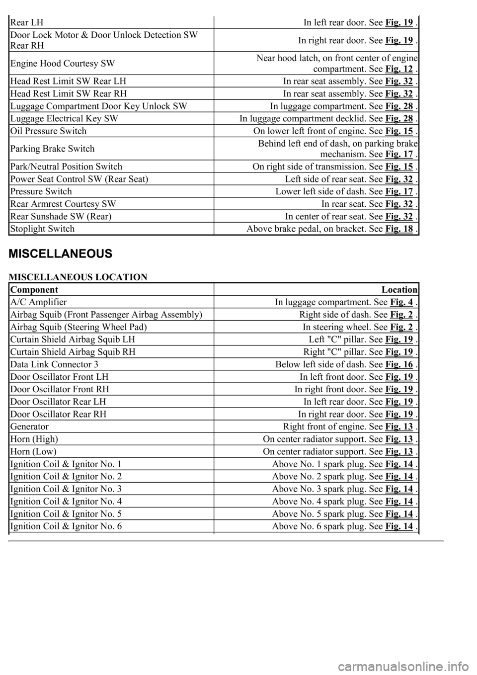
MISCELLANEOUS LOCATION
Rear LHIn left rear door. See Fig. 19 .
Door Lock Motor & Door Unlock Detection SW
Rear RHIn right rear door. See Fig. 19 .
Engine Hood Courtesy SWNear hood latch, on front center of engine
compartment. See Fig. 12
.
Head Rest Limit SW Rear LHIn rear seat assembly. See Fig. 32 .
Head Rest Limit SW Rear RHIn rear seat assembly. See Fig. 32 .
Luggage Compartment Door Key Unlock SWIn luggage compartment. See Fig. 28 .
Luggage Electrical Key SWIn luggage compartment decklid. See Fig. 28 .
Oil Pressure SwitchOn lower left front of engine. See Fig. 15 .
Parking Brake SwitchBehind left end of dash, on parking brake
mechanism. See Fig. 17
.
Park/Neutral Position SwitchOn right side of transmission. See Fig. 15 .
Power Seat Control SW (Rear Seat)Left side of rear seat. See Fig. 32 .
Pressure SwitchLower left side of dash. See Fig. 17 .
Rear Armrest Courtesy SWIn rear seat. See Fig. 32 .
Rear Sunshade SW (Rear)In center of rear seat. See Fig. 32 .
Stoplight SwitchAbove brake pedal, on bracket. See Fig. 18 .
ComponentLocation
A/C AmplifierIn luggage compartment. See Fig. 4 .
Airbag Squib (Front Passenger Airbag Assembly)Right side of dash. See Fig. 2 .
Airbag Squib (Steering Wheel Pad)In steering wheel. See Fig. 2 .
Curtain Shield Airbag Squib LHLeft "C" pillar. See Fig. 19 .
Curtain Shield Airbag Squib RHRight "C" pillar. See Fig. 19 .
Data Link Connector 3Below left side of dash. See Fig. 16 .
Door Oscillator Front LHIn left front door. See Fig. 19 .
Door Oscillator Front RHIn right front door. See Fig. 19 .
Door Oscillator Rear LHIn left rear door. See Fig. 19 .
Door Oscillator Rear RHIn right rear door. See Fig. 19 .
GeneratorRight front of engine. See Fig. 13 .
Horn (High)On center radiator support. See Fig. 13 .
Horn (Low)On center radiator support. See Fig. 13 .
Ignition Coil & Ignitor No. 1Above No. 1 spark plug. See Fig. 14 .
Ignition Coil & Ignitor No. 2Above No. 2 spark plug. See Fig. 14 .
Ignition Coil & Ignitor No. 3Above No. 3 spark plug. See Fig. 14 .
Ignition Coil & Ignitor No. 4Above No. 4 spark plug. See Fig. 14 .
Ignition Coil & Ignitor No. 5Above No. 5 spark plug. See Fig. 14 .
Ignition Coil & Ignitor No. 6Above No. 6 spark plug. See Fig. 14 .
Page 2740 of 4500
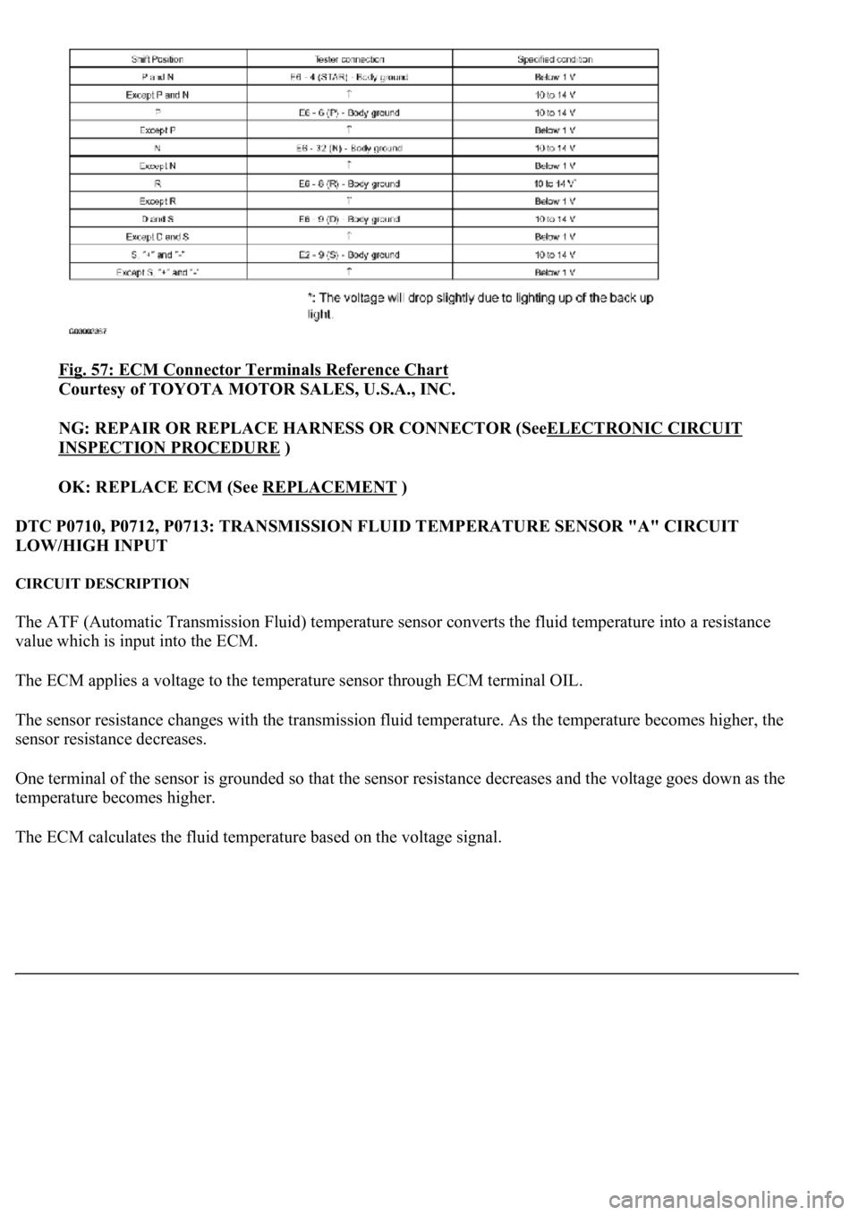
Fig. 57: ECM Connector Terminals Reference Chart
Courtesy of TOYOTA MOTOR SALES, U.S.A., INC.
NG: REPAIR OR REPLACE HARNESS OR CONNECTOR (SeeELECTRONIC CIRCUIT
INSPECTION PROCEDURE )
OK: REPLACE ECM (See REPLACEMENT
)
DTC P0710, P0712, P0713: TRANSMISSION FLUID TEMPERATURE SENSOR "A" CIRCUIT
LOW/HIGH INPUT
CIRCUIT DESCRIPTION
The ATF (Automatic Transmission Fluid) temperature sensor converts the fluid temperature into a resistance
value which is input into the ECM.
The ECM applies a voltage to the temperature sensor through ECM terminal OIL.
The sensor resistance changes with the transmission fluid temperature. As the temperature becomes higher, the
sensor resistance decreases.
One terminal of the sensor is grounded so that the sensor resistance decreases and the voltage goes down as the
temperature becomes higher.
The ECM calculates the fluid temperature based on the volta
ge signal.
Page 2745 of 4500
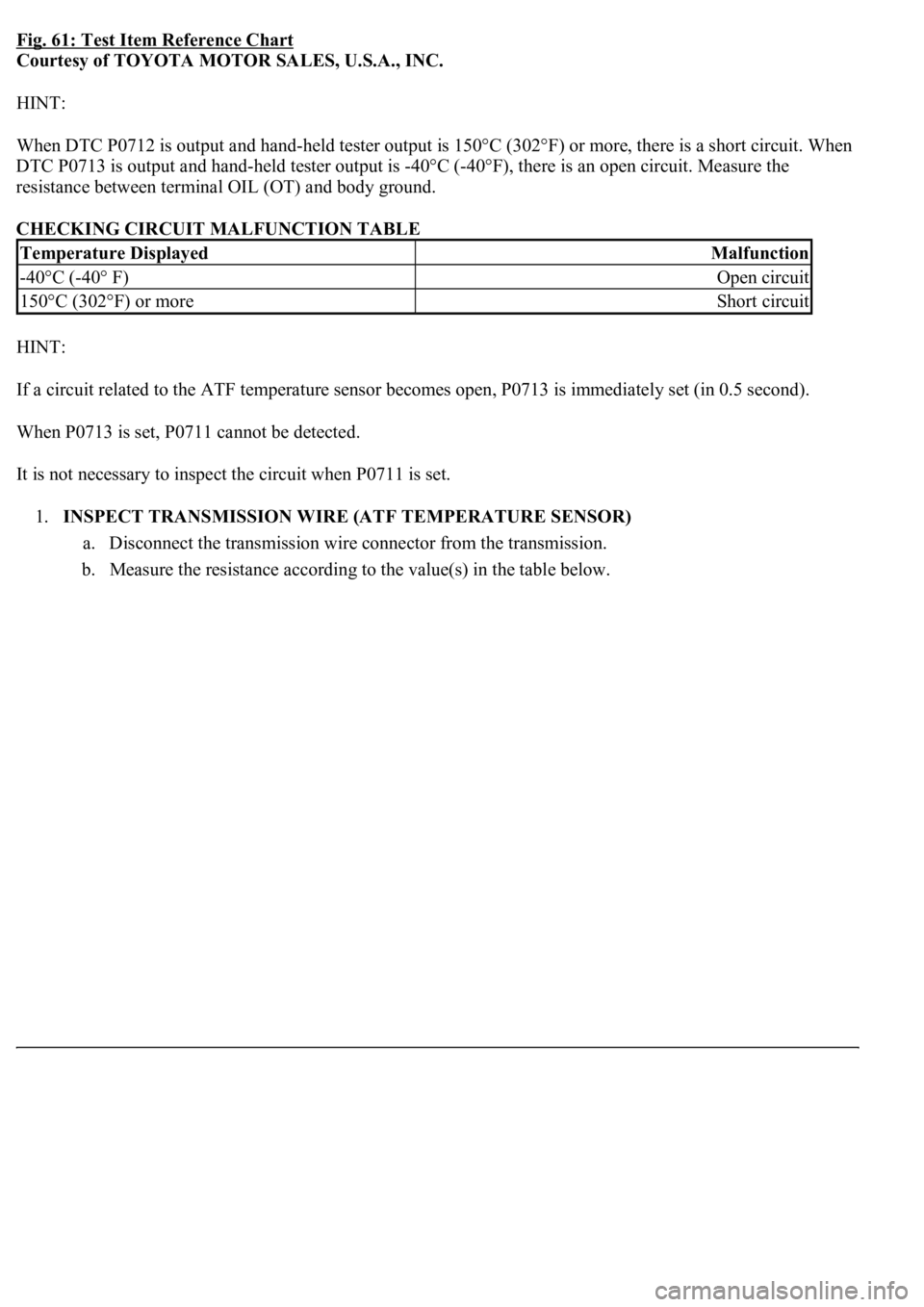
Fig. 61: Test Item Reference Chart
Courtesy of TOYOTA MOTOR SALES, U.S.A., INC.
HINT:
<003a004b004800510003002700370026000300330013001a001400150003004c0056000300520058005700530058005700030044005100470003004b0044005100470010004b0048004f004700030057004800560057004800550003005200580057005300
5800570003004c00560003001400180013008300260003000b[302°F) or more, there is a short circuit. When
DTC P0713 is output and hand-held tester output is -40°C (-40°F), there is an open circuit. Measure the
resistance between terminal OIL (OT) and body ground.
CHECKING CIRCUIT MALFUNCTION TABLE
HINT:
If a circuit related to the ATF temperature sensor becomes open, P0713 is immediately set (in 0.5 second).
When P0713 is set, P0711 cannot be detected.
It is not necessary to inspect the circuit when P0711 is set.
1.INSPECT TRANSMISSION WIRE (ATF TEMPERATURE SENSOR)
a. Disconnect the transmission wire connector from the transmission.
b. Measure the resistance according to the value(s) in the table below.
Temperature DisplayedMalfunction
-40°C (-40° F)Open circuit
150°C (302°F) or moreShort circuit
Page 2747 of 4500
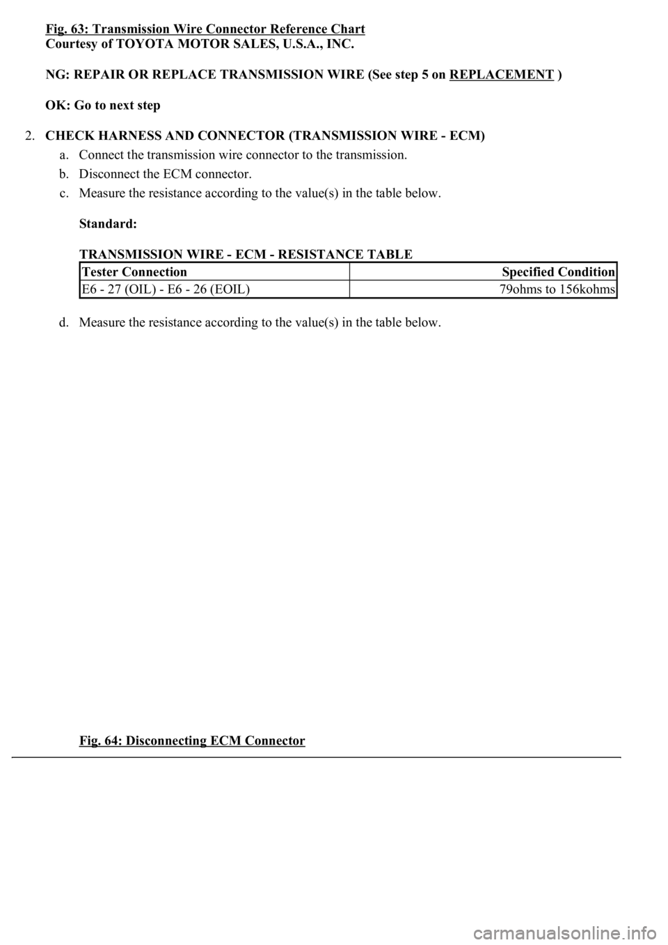
Fig. 63: Transmission Wire Connector Reference Chart
Courtesy of TOYOTA MOTOR SALES, U.S.A., INC.
NG: REPAIR OR REPLACE TRANSMISSION WIRE (See step 5 on REPLACEMENT
)
OK: Go to next step
2.CHECK HARNESS AND CONNECTOR (TRANSMISSION WIRE - ECM)
a. Connect the transmission wire connector to the transmission.
b. Disconnect the ECM connector.
c. Measure the resistance according to the value(s) in the table below.
Standard:
TRANSMISSION WIRE - ECM - RESISTANCE TABLE
d. Measure the resistance according to the value(s) in the table below.
Fig. 64: Disconnecting ECM Connector
Tester ConnectionSpecified Condition
E6 - 27 (OIL) - E6 - 26 (EOIL)79ohms to 156kohms