Page 574 of 4500
HINT:
If DTC C1741 (AIR SUS relay circuit) is displayed, carry out the inspection necessary (SEE DTC C1741
AIR SUS RELAY CIRCUIT ).
NG: REPAIR CIRCUIT INDICATED BY OUTPUT CODE
OK:Go to next step
2.INSPECT HEIGHT CONTROL COMPRESSOR MOTOR
a. Disconnect the height control compressor motor connector.
b. Connect terminal 1 (B) to the battery positive (+) terminal, and terminal 2 (E) to the battery
negative (-) terminal.
c. Check the operating sound of the compressor motor.
OK:
Compressor motor operates.
HINT:
When a malfunction is found in the height control compressor motor, replace the height control
compressor assy.
NG: REPLACE HEIGHT CONTROL COMPRESSOR ASSY (SEE REPLACEMENT
)
OK:Go to next step
Page 585 of 4500
RESULT DESCRIPTION
HINT:
When a malfunction is found in the rear solenoid valve, replace the height control valve sub-assy No. 2.
B: REPLACE HEIGHT CONTROL VALVE SUB-ASSY NO. 1 (SEE REPLACEMENT
)
C: REPLACE HEIGHT CONTROL VALVE SUB-ASSY NO. 2 (SEE REPLACEMENT
)
A:Go to next step
Fig. 102: Identifying Height Control Solenoid Valve Rear LH Connector Terminals
Courtesy of TOYOTA MOTOR SALES, U.S.A., INC.
9.INSPECT EXHAUST SOLENOID VALVE
a. Disconnect the exhaust solenoid valve connector.
b. Connect terminal 1 (SLEX) to the battery positive (+) terminal, and terminal 2 (GND) to the battery
ne
gative (-) terminal.
OKA
NGC
Page 592 of 4500
Fig. 108: Identifying Height Control Solenoid Valve Rear LH Connector Terminals
Courtesy of TOYOTA MOTOR SALES, U.S.A., INC.
RESULT DESCRIPTION
HINT:
When a malfunction is found in the rear solenoid valve, replace the height control valve sub-assy No. 2.
B: REPLACE HEIGHT CONTROL VALVE SUB-ASSY NO. 1 (SEE REPLACEMENT
)
C: REPLACE HEIGHT CONTROL VALVE SUB-ASSY NO. 2 (SEE REPLACEMENT
)
A:Go to next step
5.INSPECT EXHAUST SOLENOID VALVE
a. Disconnect the exhaust solenoid valve connector.
b. Connect terminal 3 (SLEX) to the battery positive (+) terminal, and terminal 2 (GND) to the battery
ne
gative (-) terminal.
OKA
NGC
Page 598 of 4500
Fig. 113: Identifying Suspension Control ECU Connector Terminals
Courtesy of TOYOTA MOTOR SALES, U.S.A., INC.
NG: CHECK POWER SOURCE CIRCUIT (SEE DTC C1774 POWER SOURCE CIRCUIT
)
OK: REPLACE SUSPENSION CONTROL ECU (SEE REPLACEMENT
)
CIRCUIT DESCRIPTION
When the ignition switch is turned to the ON position, the D-IG1 relay is activated and battery voltage is
applied to terminal B of the suspension control ECU. When the ignition switch is turned off, the D-IG1 relay is
de-energized and the power source is cut off.
This power source energizes the suspension control actuator, height control solenoid valve, D-IG1 relay, each
IC and sensor.
Page 644 of 4500
Fig. 10: Identifying Radio Receiver Assy Screws And Brackets
Courtesy of TOYOTA MOTOR SALES, U.S.A., INC.
7.INSTALL RADIO RECEIVER ASSEMBLY W/BRACKET
a. Make sure that the battery negative terminal is disconnected.
b. Connect the connector.
c. Install the radio receiver assembly with the 2 bolts.
REPLACEMENT
HINT:
See COMPONENTS .
See LOCATION .
Installation is in the reverse order of removal.
Page 825 of 4500

7.TRANSMISSION
a. Install the overflow plug.
b. Stop the engine.
c. Remove the refill plug.
d. Add 0.4 liters (0.42 US qts, 0.35 Imp. qts) of fluid.
e. Allow the engine to idle and wait for 10 seconds.
f. Proceed to next step.
8.COMPLETE
a. Install the overflow plug with a new gasket.
b. Stop the engine.
c. Install the refill plug with a new gasket.
d. Install the transmission case cover with the two bolts.
Torque:
20 N.m (204 kgf.cm, 15 ft.lbf) for overflow plug
39 N.m (400 kgf.cm, 53 ft.lbf) for refill plug
REPLACEMENT
1.DISCONNECT BATTERY NEGATIVE TERMINAL
2.REMOVE INSTRUMENT PANEL UNDER COVER SUB-ASSY NO.2 (SEE REPLACEMENT
)
3.REMOVE INSTRUMENT PANEL GARNISH SUB-ASSY LH (SEE REPLACEMENT
)
4.REMOVE INSTRUMENT PANEL FINISH PANEL (SEE REPLACEMENT
)
5.REMOVE INSTRUMENT PANEL UNDER COVER SUB-ASSY NO.1 (SEE REPLACEMENT
)
6.REMOVE SWITCH BRACE HOLE COVER (SEE REPLACEMENT
)
7.REMOVE INSTRUMENT PANEL SAFETY PAD SUB-ASSY NO.1 (SEE REPLACEMENT
)
8.REMOVE INSTRUMENT PANEL CUP HOLDER ASSY (SEE REPLACEMENT
)
9.REMOVE CONSOLE UPPER REAR PANEL SUB-ASSY (SEE REPLACEMENT
)
10.REMOVE CONSOLE BOX CARPET (SEE REPLACEMENT
)
11.REMOVE REAR CONSOLE ARMREST ASSY (SEE REPLACEMENT
)
12.REMOVE INSTRUMENT PANEL FINISH PANEL LOWER CENTER (SEE REPLACEMENT
)
13.REMOVE INSTRUMENT CLUSTER FINISH PANEL SUB-ASSY CENTER (SEE
REPLACEMENT
)
14.REMOVE CONSOLE PANEL SUB-ASSY UPPER (SEE REPLACEMENT
)
15.REMOVE CONSOLE BOX (SEE REPLACEMENT
)
16.SEPARATE OXYGEN SENSOR (SEE REPLACEMENT
)
Page 838 of 4500

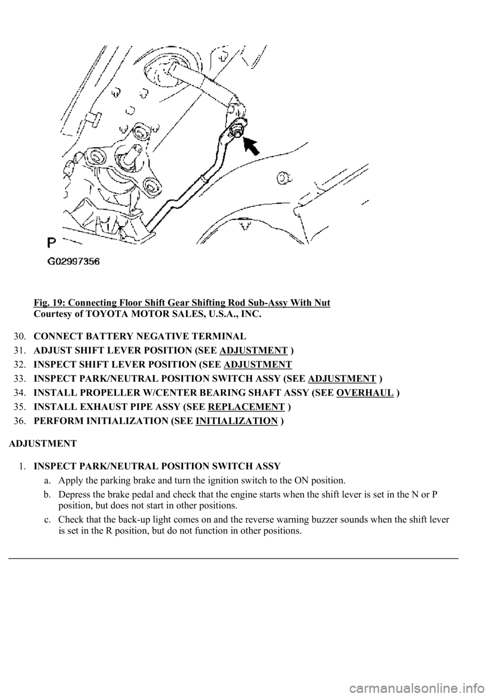
<0029004c004a001100030014001c001d00030026005200510051004800460057004c0051004a00030029004f00520052005500030036004b004c004900570003002a00480044005500030036004b004c00490057004c0051004a0003003500520047000300
3600580045[-Assy With Nut
Courtesy of TOYOTA MOTOR SALES, U.S.A., INC.
30.CONNECT BATTERY NEGATIVE TERMINAL
31.ADJUST SHIFT LEVER POSITION (SEE ADJUSTMENT
)
32.INSPECT SHIFT LEVER POSITION (SEE ADJUSTMENT
33.INSPECT PARK/NEUTRAL POSITION SWITCH ASSY (SEE ADJUSTMENT
)
34.INSTALL PROPELLER W/CENTER BEARING SHAFT ASSY (SEE OVERHAUL
)
35.INSTALL EXHAUST PIPE ASSY (SEE REPLACEMENT
)
36.PERFORM INITIALIZATION (SEE INITIALIZATION
)
ADJUSTMENT
1.INSPECT PARK/NEUTRAL POSITION SWITCH ASSY
a. Apply the parking brake and turn the ignition switch to the ON position.
b. Depress the brake pedal and check that the engine starts when the shift lever is set in the N or P
position, but does not start in other positions.
c. Check that the back-up light comes on and the reverse warning buzzer sounds when the shift lever
is set in the R position, but do not function in other positions.
Page 844 of 4500
Fig. 25: Identifying Automatic Transmission Assy Components
Courtesy of TOYOTA MOTOR SALES, U.S.A., INC.
REPLACEMENT
1.DISCONNECT BATTERY NEGATIVE TERMINAL
2.REMOVE ENGINE UNDER COVER NO.1