Page 598 of 4500
Fig. 113: Identifying Suspension Control ECU Connector Terminals
Courtesy of TOYOTA MOTOR SALES, U.S.A., INC.
NG: CHECK POWER SOURCE CIRCUIT (SEE DTC C1774 POWER SOURCE CIRCUIT
)
OK: REPLACE SUSPENSION CONTROL ECU (SEE REPLACEMENT
)
CIRCUIT DESCRIPTION
When the ignition switch is turned to the ON position, the D-IG1 relay is activated and battery voltage is
applied to terminal B of the suspension control ECU. When the ignition switch is turned off, the D-IG1 relay is
de-energized and the power source is cut off.
This power source energizes the suspension control actuator, height control solenoid valve, D-IG1 relay, each
IC and sensor.
Page 605 of 4500
Fig. 120: Identifying Suspension Control ECU Connector Terminals
Courtesy of TOYOTA MOTOR SALES, U.S.A., INC.
NG: REPAIR OR REPLACE HARNESS OR CONNECTOR
OK: REPLACE SUSPENSION CONTROL ECU (SEE REPLACEMENT
)
CIRCUIT DESCRIPTION
The speed sensors monitors the speed of the wheels, and sends an appropriate speed signals to the suspension
control ECU through the brake actuator assy (skid control ECU).
If trouble occurs in either the right rear speed sensor or left rear speed sensor, DTC (C1776) is output.
Page 1199 of 4500

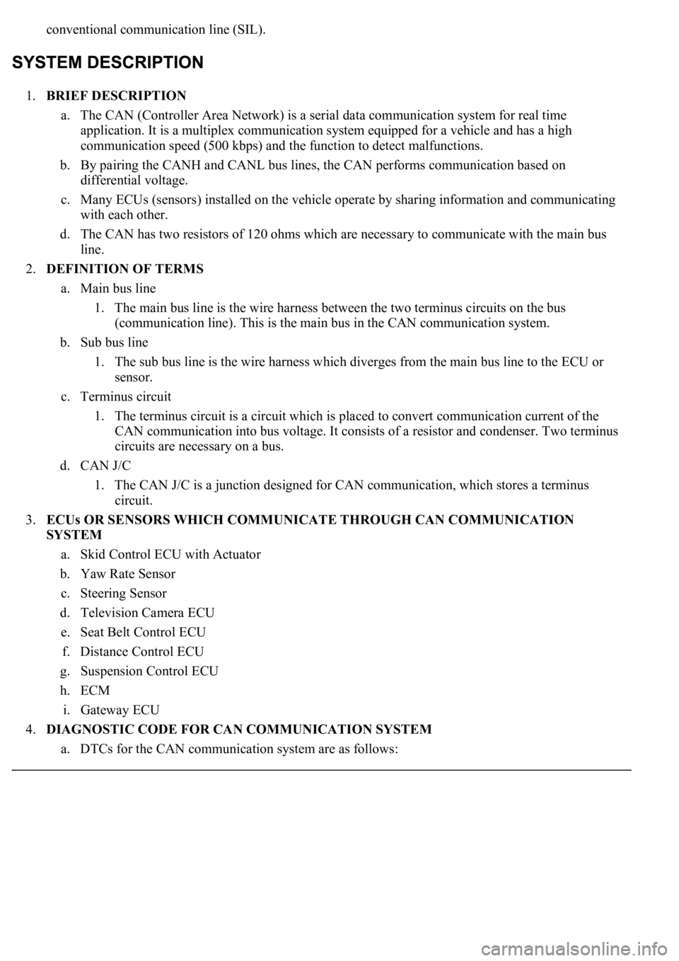
conventional communication line (SIL).
1.BRIEF DESCRIPTION
a. The CAN (Controller Area Network) is a serial data communication system for real time
application. It is a multiplex communication system equipped for a vehicle and has a high
communication speed (500 kbps) and the function to detect malfunctions.
b. By pairing the CANH and CANL bus lines, the CAN performs communication based on
differential voltage.
c. Many ECUs (sensors) installed on the vehicle operate by sharing information and communicating
with each other.
d. The CAN has two resistors of 120 ohms which are necessary to communicate with the main bus
line.
2.DEFINITION OF TERMS
a. Main bus line
1. The main bus line is the wire harness between the two terminus circuits on the bus
(communication line). This is the main bus in the CAN communication system.
b. Sub bus line
1. The sub bus line is the wire harness which diverges from the main bus line to the ECU or
sensor.
c. Terminus circuit
1. The terminus circuit is a circuit which is placed to convert communication current of the
CAN communication into bus voltage. It consists of a resistor and condenser. Two terminus
circuits are necessary on a bus.
d. CAN J/C
1. The CAN J/C is a junction designed for CAN communication, which stores a terminus
circuit.
3.ECUs OR SENSORS WHICH COMMUNICATE THROUGH CAN COMMUNICATION
SYSTEM
a. Skid Control ECU with Actuator
b. Yaw Rate Sensor
c. Steering Sensor
d. Television Camera ECU
e. Seat Belt Control ECU
f. Distance Control ECU
g. Suspension Control ECU
h. ECM
i. Gateway ECU
4.DIAGNOSTIC CODE FOR CAN COMMUNICATION SYSTEM
a. DTCs for the CAN communication system are as follows:
Page 2631 of 4500

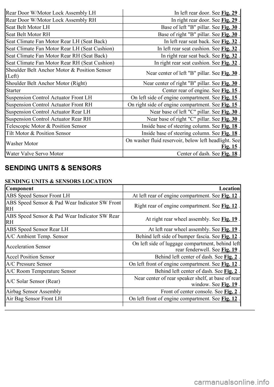
SENDING UNITS & SENSORS LOCATION
Rear Door W/Motor Lock Assembly LHIn left rear door. See Fig. 29 .
Rear Door W/Motor Lock Assembly RHIn right rear door. See Fig. 29 .
Seat Belt Motor LHBase of left "B" pillar. See Fig. 30 .
Seat Belt Motor RHBase of right "B" pillar. See Fig. 30 .
Seat Climate Fan Motor Rear LH (Seat Back)In left rear seat back. See Fig. 32 .
Seat Climate Fan Motor Rear LH (Seat Cushion)In left rear seat cushion. See Fig. 32 .
Seat Climate Fan Motor Rear RH (Seat Back)In right rear seat back. See Fig. 32 .
Seat Climate Fan Motor Rear RH (Seat Cushion)In right rear seat cushion. See Fig. 32 .
Shoulder Belt Anchor Motor & Position Sensor
(Left)Near center of left "B" pillar. See Fig. 30 .
Shoulder Belt Anchor Motor (Right)Near center of right "B" pillar. See Fig. 30 .
StarterCenter rear of engine. See Fig. 15 .
Suspension Control Actuator Front LHOn left side of engine compartment. See Fig. 15 .
Suspension Control Actuator Front RHOn right side of engine compartment. See Fig. 15 .
Suspension Control Actuator Rear LHNear base of left "C" pillar. See Fig. 30 .
Suspension Control Actuator Rear RHNear base of right "C" pillar. See Fig. 30 .
Telescopic Motor & Position SensorInside base of steering column. See Fig. 18 .
Tilt Motor & Position SensorInside base of steering column. See Fig. 18 .
Washer MotorOn washer fluid reservoir, below left headlight. See
Fig. 15
.
Water Valve Servo MotorCenter of dash. See Fig. 18 .
ComponentLocation
ABS Speed Sensor Front LHAt left rear of engine compartment. See Fig. 12 .
ABS Speed Sensor & Pad Wear Indicator SW Front
RHRight rear of engine compartment. See Fig. 12 .
ABS Speed Sensor & Pad Wear Indicator SW Rear
RHAt right rear wheel assembly. See Fig. 19 .
ABS Speed Sensor Rear LHAt left rear wheel assembly. See Fig. 19 .
A/C Ambient Temp. SensorBehind left side of bumper fascia. See Fig. 12 .
Acceleration SensorOn left side of luggage compartment, behind left
rear fenderwell. See Fig. 19
.
Accel Position SensorBehind left center of dash. See Fig. 2 .
A/C Pressure SensorOn left front of engine compartment. See Fig. 12 .
A/C Room Temperature SensorBehind left center of dash. See Fig. 2 .
A/C Solar Sensor (Rear)Near center of rear speaker shelf, at base of rear
window. See Fig. 19
.
Airbag Sensor AssemblyFront of center console. See Fig. 2 .
Air Bag Sensor Front LHOn left front of engine compartment. See Fig. 12 .
Page 4010 of 4500
Fig. 18: Removing Absorber Control Actuator
Courtesy of TOYOTA MOTOR SALES, U.S.A., INC.
4.REMOVE HEIGHT CONTROL SENSOR SUB-ASSY FRONT LH
5.SEPARATE FRONT STABILIZER LINK ASSY LH
a. Support the suspension lower arm with a jack using a wood block to avoid damage.
b. Remove the nut and washer and separate the stabilizer link assy LH.