Page 2420 of 4500

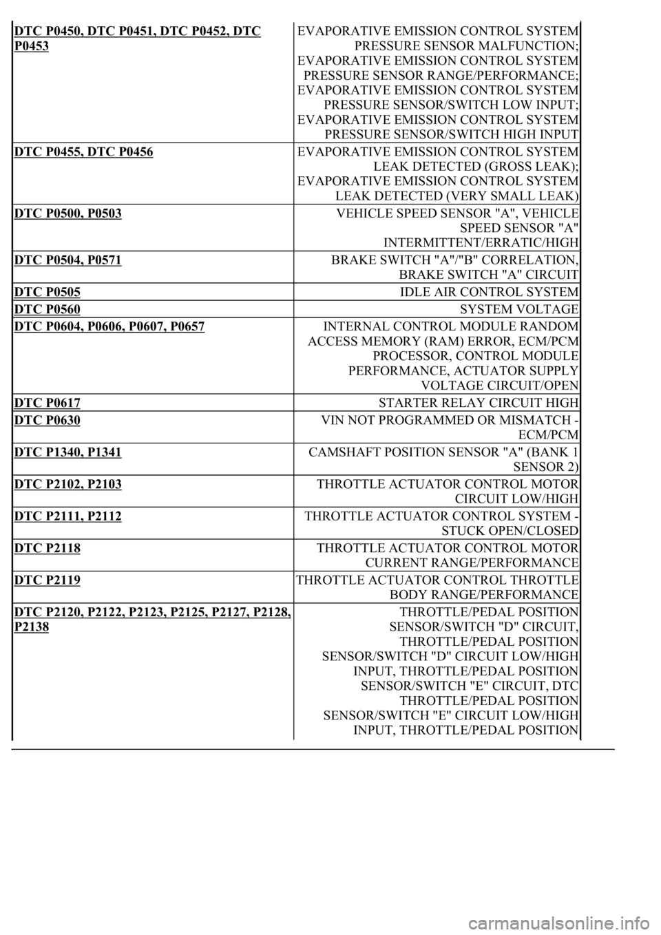
DTC P0450, DTC P0451, DTC P0452, DTC
P0453
EVAPORATIVE EMISSION CONTROL SYSTEM
PRESSURE SENSOR MALFUNCTION;
EVAPORATIVE EMISSION CONTROL SYSTEM
PRESSURE SENSOR RANGE/PERFORMANCE;
EVAPORATIVE EMISSION CONTROL SYSTEM
PRESSURE SENSOR/SWITCH LOW INPUT;
EVAPORATIVE EMISSION CONTROL SYSTEM
PRESSURE SENSOR/SWITCH HIGH INPUT
DTC P0455, DTC P0456 EVAPORATIVE EMISSION CONTROL SYSTEM
LEAK DETECTED (GROSS LEAK);
EVAPORATIVE EMISSION CONTROL SYSTEM
LEAK DETECTED (VERY SMALL LEAK)
DTC P0500, P0503 VEHICLE SPEED SENSOR "A", VEHICLE
SPEED SENSOR "A"
INTERMITTENT/ERRATIC/HIGH
DTC P0504, P0571 BRAKE SWITCH "A"/"B" CORRELATION,
BRAKE SWITCH "A" CIRCUIT
DTC P0505 IDLE AIR CONTROL SYSTEM
DTC P0560 SYSTEM VOLTAGE
DTC P0604, P0606, P0607, P0657 INTERNAL CONTROL MODULE RANDOM
ACCESS MEMORY (RAM) ERROR, ECM/PCM
PROCESSOR, CONTROL MODULE
PERFORMANCE, ACTUATOR SUPPLY
VOLTAGE CIRCUIT/OPEN
DTC P0617 STARTER RELAY CIRCUIT HIGH
DTC P0630 VIN NOT PROGRAMMED OR MISMATCH -
ECM/PCM
DTC P1340, P1341 CAMSHAFT POSITION SENSOR "A" (BANK 1
SENSOR 2)
DTC P2102, P2103 THROTTLE ACTUATOR CONTROL MOTOR
CIRCUIT LOW/HIGH
DTC P2111, P2112 THROTTLE ACTUATOR CONTROL SYSTEM -
STUCK OPEN/CLOSED
DTC P2118 THROTTLE ACTUATOR CONTROL MOTOR
CURRENT RANGE/PERFORMANCE
DTC P2119 THROTTLE ACTUATOR CONTROL THROTTLE
BODY RANGE/PERFORMANCE
DTC P2120, P2122, P2123, P2125, P2127, P2128,
P2138
THROTTLE/PEDAL POSITION
SENSOR/SWITCH "D" CIRCUIT,
THROTTLE/PEDAL POSITION
SENSOR/SWITCH "D" CIRCUIT LOW/HIGH
INPUT, THROTTLE/PEDAL POSITION
SENSOR/SWITCH "E" CIRCUIT, DTC
THROTTLE/PEDAL POSITION
SENSOR/SWITCH "E" CIRCUIT LOW/HIGH
INPUT, THROTTLE/PEDAL POSITION
Page 2437 of 4500

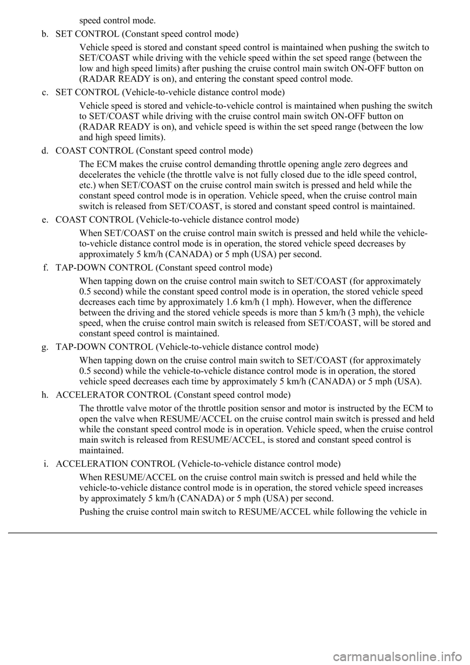
speed control mode.
b. SET CONTROL (Constant speed control mode)
Vehicle speed is stored and constant speed control is maintained when pushing the switch to
SET/COAST while driving with the vehicle speed within the set speed range (between the
low and high speed limits) after pushing the cruise control main switch ON-OFF button on
(RADAR READY is on), and entering the constant speed control mode.
c. SET CONTROL (Vehicle-to-vehicle distance control mode)
Vehicle speed is stored and vehicle-to-vehicle control is maintained when pushing the switch
to SET/COAST while driving with the cruise control main switch ON-OFF button on
(RADAR READY is on), and vehicle speed is within the set speed range (between the low
and high speed limits).
d. COAST CONTROL (Constant speed control mode)
The ECM makes the cruise control demanding throttle opening angle zero degrees and
decelerates the vehicle (the throttle valve is not fully closed due to the idle speed control,
etc.) when SET/COAST on the cruise control main switch is pressed and held while the
constant speed control mode is in operation. Vehicle speed, when the cruise control main
switch is released from SET/COAST, is stored and constant speed control is maintained.
e. COAST CONTROL (Vehicle-to-vehicle distance control mode)
When SET/COAST on the cruise control main switch is pressed and held while the vehicle-
to-vehicle distance control mode is in operation, the stored vehicle speed decreases by
approximately 5 km/h (CANADA) or 5 mph (USA) per second.
f. TAP-DOWN CONTROL (Constant speed control mode)
When tapping down on the cruise control main switch to SET/COAST (for approximately
0.5 second) while the constant speed control mode is in operation, the stored vehicle speed
decreases each time by approximately 1.6 km/h (1 mph). However, when the difference
between the driving and the stored vehicle speeds is more than 5 km/h (3 mph), the vehicle
speed, when the cruise control main switch is released from SET/COAST, will be stored and
constant speed control is maintained.
g. TAP-DOWN CONTROL (Vehicle-to-vehicle distance control mode)
When tapping down on the cruise control main switch to SET/COAST (for approximately
0.5 second) while the vehicle-to-vehicle distance control mode is in operation, the stored
vehicle speed decreases each time by approximately 5 km/h (CANADA) or 5 mph (USA).
h. ACCELERATOR CONTROL (Constant speed control mode)
The throttle valve motor of the throttle position sensor and motor is instructed by the ECM to
open the valve when RESUME/ACCEL on the cruise control main switch is pressed and held
while the constant speed control mode is in operation. Vehicle speed, when the cruise control
main switch is released from RESUME/ACCEL, is stored and constant speed control is
maintained.
i. ACCELERATION CONTROL (Vehicle-to-vehicle distance control mode)
When RESUME/ACCEL on the cruise control main switch is pressed and held while the
vehicle-to-vehicle distance control mode is in operation, the s
tored vehicle speed increases
by approximately 5 km/h (CANADA) or 5 mph (USA) per second.
Pushin
g the cruise control main switch to RESUME/ACCEL while following the vehicle in
Page 2438 of 4500

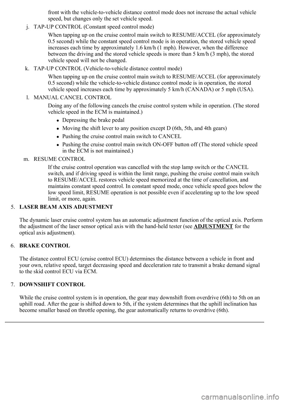
front with the vehicle-to-vehicle distance control mode does not increase the actual vehicle
speed, but changes only the set vehicle speed.
j. TAP-UP CONTROL (Constant speed control mode)
When tapping up on the cruise control main switch to RESUME/ACCEL (for approximately
0.5 second) while the constant speed control mode is in operation, the stored vehicle speed
increases each time by approximately 1.6 km/h (1 mph). However, when the difference
between the driving and the stored vehicle speeds is more than 5 km/h (3 mph), the stored
vehicle speed will not be changed.
k. TAP-UP CONTROL (Vehicle-to-vehicle distance control mode)
When tapping up on the cruise control main switch to RESUME/ACCEL (for approximately
0.5 second) while the vehicle-to-vehicle distance control mode is in operation, the stored
vehicle speed increases each time by approximately 5 km/h (CANADA) or 5 mph (USA).
l. MANUAL CANCEL CONTROL
<00270052004c0051004a000300440051005c00030052004900030057004b0048000300490052004f004f0052005a004c0051004a000300460044005100460048004f005600030057004b00480003004600550058004c005600480003004600520051005700
550052004f00030056005c00560057004800500003005a004b[ile in operation. (The stored
vehicle speed in the ECM is maintained.)
Depressing the brake pedal
<003000520059004c0051004a00030057004b004800030056004b004c004900570003004f0048005900480055000300570052000300440051005c0003005300520056004c0057004c0052005100030048005b0046004800530057000300270003000b001900
57004b000f000300180057004b000f00030044005100470003[4th gears)
Pushing the cruise control main switch to CANCEL
Pushing the cruise control main switch ON-OFF button off (The stored vehicle speed
in the ECM is not maintained.)
m. RESUME CONTROL
If the cruise control operation was cancelled with the stop lamp switch or the CANCEL
switch, and if driving speed is within the limit range, pushing the cruise control main switch
to RESUME/ACCEL restores vehicle speed memorized at the time of cancellation, and
maintains constant speed control. In constant speed mode, once vehicle speed goes below the
low speed limit, RESUME operation is not possible even if accelerating up to the low speed
limit, or more, again.
5.LASER BEAM AXIS ADJUSTMENT
The dynamic laser cruise control system has an automatic adjustment function of the optical axis. Perform
the adjustment of the laser sensor optical axis with the hand-held tester (see ADJUSTMENT
for the
optical axis adjustment).
6.BRAKE CONTROL
The distance control ECU (cruise control ECU) determines the distance between a vehicle in front and
your own, relative speed, target decreasing speed and deceleration rate to transmit a brake demand signal
to the skid control ECU via ECM.
7.DOWNSHIFT CONTROL
While the cruise control system is in operation, the gear may downshift from overdrive (6th) to 5th on an
uphill road. After the gear is shifted down to 5th, if the system determines that the uphill inclination has
become smaller based on throttle opening, the gear automatically returns to overdrive (6th).
Page 2439 of 4500

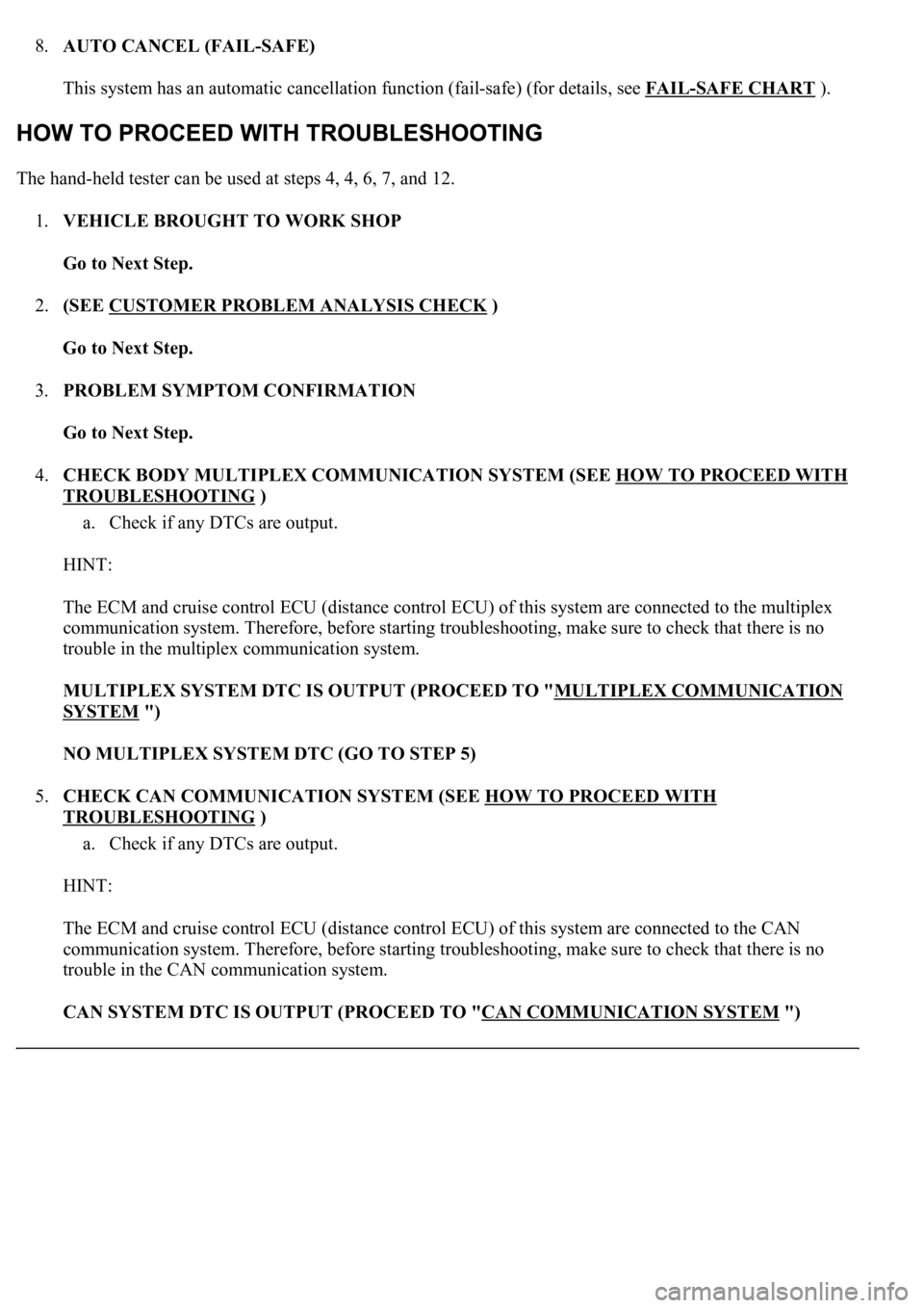
8.AUTO CANCEL (FAIL-SAFE)
This system has an automatic cancellation function (fail-safe) (for details, see FAIL
-SAFE CHART ).
The hand-held tester can be used at steps 4, 4, 6, 7, and 12.
1.VEHICLE BROUGHT TO WORK SHOP
Go to Next Step.
2.(SEE CUSTOMER PROBLEM ANALYSIS CHECK
)
Go to Next Step.
3.PROBLEM SYMPTOM CONFIRMATION
Go to Next Step.
4.CHECK BODY MULTIPLEX COMMUNICATION SYSTEM (SEE HOW TO PROCEED WITH
TROUBLESHOOTING )
a. Check if any DTCs are output.
HINT:
The ECM and cruise control ECU (distance control ECU) of this system are connected to the multiplex
communication system. Therefore, before starting troubleshooting, make sure to check that there is no
trouble in the multiplex communication system.
MULTIPLEX SYSTEM DTC IS OUTPUT (PROCEED TO "MULTIPLEX COMMUNICATION
SYSTEM ")
NO MULTIPLEX SYSTEM DTC (GO TO STEP 5)
5.CHECK CAN COMMUNICATION SYSTEM (SEE HOW TO PROCEED WITH
TROUBLESHOOTING )
a. Check if any DTCs are output.
HINT:
The ECM and cruise control ECU (distance control ECU) of this system are connected to the CAN
communication system. Therefore, before starting troubleshooting, make sure to check that there is no
trouble in the CAN communication system.
CAN SYSTEM DTC IS OUTPUT (PROCEED TO "CAN COMMUNICATION SYSTEM
")
Page 2454 of 4500
Fig. 22: Signal Waveform Graph (Waveform 2)
Courtesy of TOYOTA MOTOR SALES, U.S.A., INC.
c.ECM
Fig. 23: Identifying ECM Terminals
Courtesy of TOYOTA MOTOR SALES, U.S.A., INC.
Page 2455 of 4500
Fig. 24: ECM Terminals Voltage And Resistance Chart
Courtesy of TOYOTA MOTOR SALES, U.S.A., INC.
If the value is not within the standard range, some defects on the vehicle are suspected.
d.LASER SENSOR
Page 2458 of 4500
Fig. 27: Signal Waveform Graph (Waveform 2)
Courtesy of TOYOTA MOTOR SALES, U.S.A., INC.
1.DIAGNOSIS FUNCTION
a. The diagnosis function makes the master warning light and the multi-information display come on,
and the CRUISE main indicator light blinks as shown in the illustration. When a malfunction
occurs in the dynamic laser cruise control system, the DTCs are stored in the ECM.
Page 2460 of 4500
Fig. 29: Identifying Blinking Pattern Of CRUISE Main Indicator Light
Courtesy of TOYOTA MOTOR SALES, U.S.A., INC.
2.DESCRIPTION
a. The ECM controls the dynamic laser cruise control system of the vehicle. The data and DTCs
relating to the dynamic laser cruise control system can be read from the DLC3 of the vehicle. If
either DTC or CRUISE OK is not displayed in the multi-information display on the combination
meter when checking for DTCs, there may be a problem with the combination meter or the CAN
communication and multiplex communication system.
Use the hand-held tester to check and solve the problem.
3.CHECK THE DLC3
a. The vehicle's ECM uses ISO 9141-2 for communication. The terminal arrangement of the DLC3
complies with SAE J1962 and matches the ISO 9141-2 format.