Page 3962 of 4500
Fig. 35: Identifying Driving Position Memory Switch Connector Terminals
Page 3965 of 4500

Fig. 36: Identifying D24 Driver Door ECU Connector Terminals And D26 Driving Position
Memory Switch Connector Terminals
Courtesy of TOYOTA MOTOR SALES, U.S.A., INC.
NG: REPAIR AND REPLACE HARNESS AND CONNECTOR
OK: PROCEED TO NEXT CIRCUIT INSPECTION SHOWN ON PROBLEM SYMPTOMS
TABLE
1.DESCRIPTION
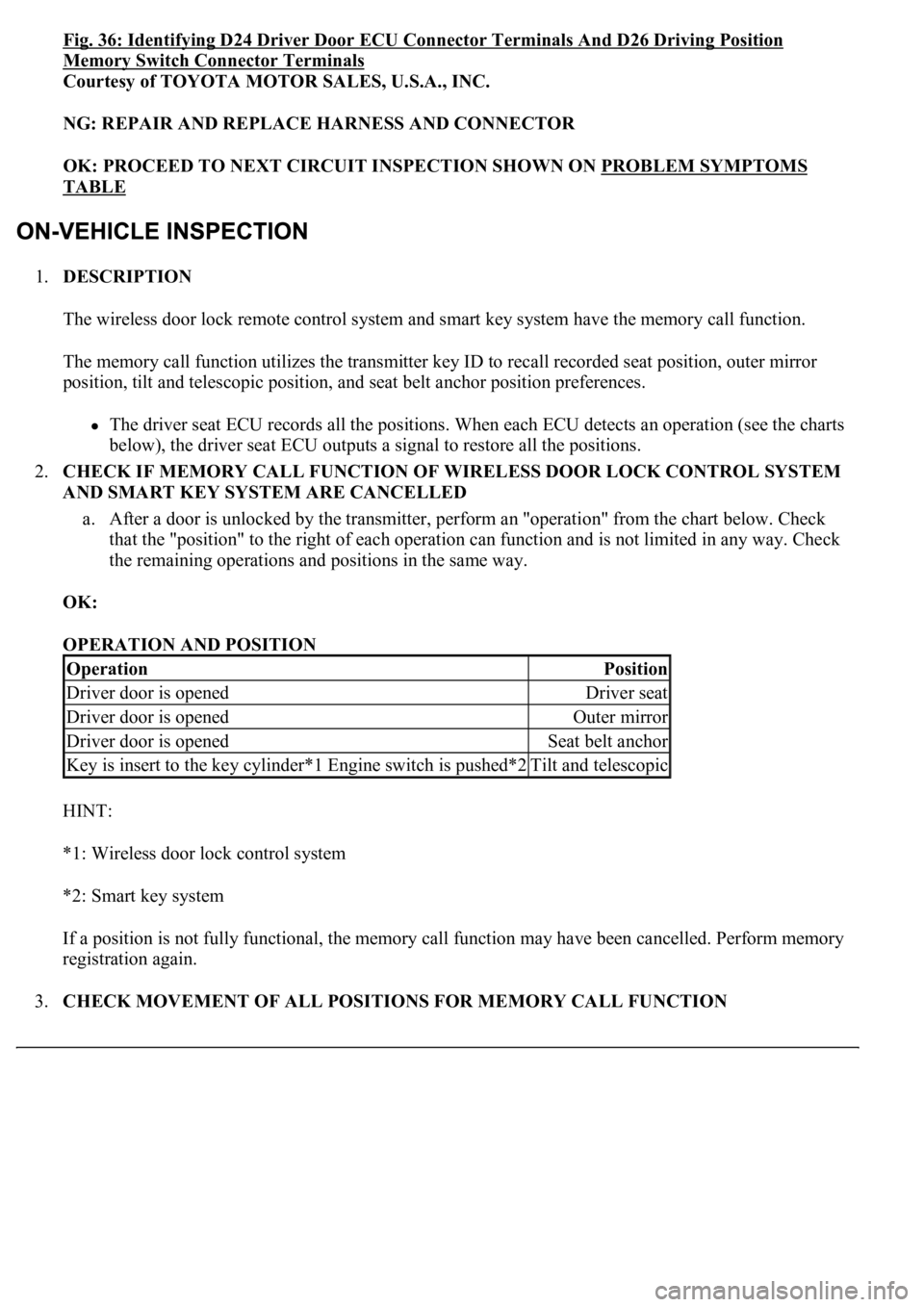
The wireless door lock remote control system and smart key system have the memory call function.
The memory call function utilizes the transmitter key ID to recall recorded seat position, outer mirror
position, tilt and telescopic position, and seat belt anchor position preferences.
The driver seat ECU records all the positions. When each ECU detects an operation (see the charts
below), the driver seat ECU outputs a signal to restore all the positions.
2.CHECK IF MEMORY CALL FUNCTION OF WIRELESS DOOR LOCK CONTROL SYSTEM
AND SMART KEY SYSTEM ARE CANCELLED
a. After a door is unlocked by the transmitter, perform an "operation" from the chart below. Check
that the "position" to the right of each operation can function and is not limited in any way. Check
<0057004b004800030055004800500044004c0051004c0051004a0003005200530048005500440057004c00520051005600030044005100470003005300520056004c0057004c0052005100560003004c005100030057004b00480003005600440050004800
03005a0044005c001100030003[
OK:
OPERATION AND POSITION
HINT:
*1: Wireless door lock control system
*2: Smart key system
If a position is not fully functional, the memory call function may have been cancelled. Perform memory
registration again.
3.CHECK MOVEMENT OF ALL POSITIONS FOR MEMORY CALL FUNCTION
OperationPosition
Driver door is openedDriver seat
Driver door is openedOuter mirror
Driver door is openedSeat belt anchor
<002e0048005c0003004c00560003004c0051005600480055005700030057005200030057004b00480003004e0048005c00030046005c004f004c0051004700480055000d0014000300280051004a004c0051004800030056005a004c00570046004b000300
4c00560003005300580056004b00480047000d0015[Tilt and telescopic
Page 3968 of 4500
Fig. 37: Identifying Front Power Seat Function
Courtesy of TOYOTA MOTOR SALES, U.S.A., INC.
5.CHECK POWER SEAT MOTOR ASSY
Page 3976 of 4500
Fig. 40: Identifying Driving Position Memory Switch Connector Terminals
Page 3979 of 4500
Fig. 41: Identifying Lumbar Support Switch Connector Terminals -Driver Seat
Courtesy of TOYOTA MOTOR SALES, U.S.A., INC.
Lower side control
TESTER CONNECTION AND SPECIFIED CONDITION
If the result is not as specified, replace the switch.
4.Passenger's seat:
INSPECT LUMBAR SUPPORT SWITCH
a. Measure the resistance between the terminals when the switch is operated.
Standard:
TESTER CONNECTION AND SPECIFIED CONDITION
If the result is not as specified, replace the switch.
Tester ConnectionSwitch ConditionSpecified Condition
2 (H1) - 5 (B)HoldBelow 1ohms
3 (R1) - 6 (E)HoldBelow 1ohms
2 (H1) - 6 (E)OFFBelow 1ohms
3 (R1) - 6 (E)OFFBelow 1ohms
2 (H1) - 6 (E)RELEASEBelow 1ohms
3 (R1) - 5 (B)RELEASEBelow 1ohms
Tester ConnectionSwitch ConditionSpecified Condition
1 (B) - 4 (H)HOLDBelow 1 ohms
2 (E) - 3 (R)HOLDBelow 1 ohms
1 (B) - 3 (R)OFFBelow 1 ohms
2 (E) - 3 (R)OFFBelow 1 ohms
1 (B) - 3 (R)RELEASEBelow 1 ohms
2 (E) - 4 (H)RELEASEBelow 1 ohms
Page 3980 of 4500
Fig. 42: Identifying Lumbar Support Switch Connector Terminals - Passenger Seat
Courtesy of TOYOTA MOTOR SALES, U.S.A., INC.
5.Driver's seat:
INSPECT POWER SEAT CUSHION SWITCH
a. Measure the resistance between the terminals when the switch is operated.
b. Remove the power seat cushion switch.
c. Measure the resistance of the switch.
Standard:
TESTER CONNECTION AND SPECIFIED CONDITION
If the result is not as specified, replace the switch.
Tester ConnectionSwitch ConditionSpecified Condition
1 (CSNF) - 4 (E)FRONTBelow 1 ohms
1 (CSNF) - 4 (E), 2 (CSNR) -4 (E)OFF10 kohms higher
2 (CSNR) - 4 (E)REARBelow 1 ohms
Page 3982 of 4500
Fig. 43: Identifying Power Seat Cushion Switch Connector Terminals -Driver Seat
Courtesy of TOYOTA MOTOR SALES, U.S.A., INC.
6.Passenger's seat:
INSPECT POWER SEAT SWITCH SUB
a. Measure the resistance between the terminals when the switch is operated.
Standard:
Reclining switch
TESTER CONNECTION AND SPECIFIED CONDITION
Slide switch
TESTER CONNECTION AND SPECIFIED CONDITION
If the result is not as specified, replace the switch.
Tester ConnectionSwitch ConditionSpecified Condition
5 (MRF) - 10 (B)FRONTBelow 1 ohms
6 (MRR) - 10 (B)FRONTBelow 1 ohms
5 (MRF) - 7 (RCLF)OFFBelow 1 ohms
2 (RCLR) - 6 (MRR)OFFBelow 1 ohms
6 (MRR) - 10 (B)REARBelow 1 ohms
5 (MRF) - 7 (RCLF)REARBelow 1 ohms
Tester ConnectionSwitch ConditionSpecified Condition
4 (MSF) - 10 (B)FRONTBelow 1 ohms
3 (SLDR) - 9 (MSR)FRONTBelow 1 ohms
4 (MSF) - 8 (SLDF)OFFBelow 1 ohms
3 (SLDR) - 9 (MSR)OFFBelow 1 ohms
9 (MSR) - 10 (B)REARBelow 1 ohms
4 (MSF) - 8 (SLDF)REARBelow 1 ohms
Page 3983 of 4500
Fig. 44: Identifying Power Seat Cushion Switch Connector Terminals - Passenger Seat
Courtesy of TOYOTA MOTOR SALES, U.S.A., INC.
7.INSPECT POWER SEAT MOTOR
a. Check operation of the slide motor.
1. Check if the motor rotates smoothly when the battery is connected to the slide motor
connector terminals.
OK:
MEASUREMENT CONDITION AND SPECIFIED CONDITION
If the result is not as specified, replace the slide motor.
Measurement ConditionSpecified Condition
Battery positive (+) --> 1 Battery negative (-) --> 2Counterclockwise
Battery positive (+) --> 2 Battery negative (-) --> 1Clockwise