Page 1541 of 4500
Fig. 30: Identifying Clearance Warning ECU Assy Terminals
Courtesy of TOYOTA MOTOR SALES, U.S.A., INC.
NG: REPAIR OR REPLACE HARNESS OR CONNECTOR
OK: REPLACE CLEARANCE WARNING ECU ASSY (SEE REPLACEMENT
)
CIRCUIT DESCRIPTION
Ultrasonic sensor consists of a sensor portion that transmits and receives ultrasonic waves and a pre-amplifier
that amplifies them. The ultrasonic sensor outputs the ultrasonic transmission and reception signals to the
clearance warning ECU assy.
Fig. 31: DTC B2234 Detection Condition And Trouble Area Description Chart
Courtesy of TOYOTA MOTOR SALES, U.S.A., INC.
WIRING DIAGRAM
Page 1545 of 4500
Fig. 34: Identifying Clearance Warning ECU Assy Terminals
Courtesy of TOYOTA MOTOR SALES, U.S.A., INC.
NG: REPAIR OR REPLACE HARNESS OR CONNECTOR
OK: REPLACE CLEARANCE WARNING ECU ASSY (SEE REPLACEMENT
)
CIRCUIT DESCRIPTION
Ultrasonic sensor consists of a sensor portion that transmits and receives ultrasonic waves and a pre-amplifier
that amplifies them. The ultrasonic sensor outputs the ultrasonic transmission and reception signals to the
clearance warning ECU assy.
Fig. 35: DTC B2235 Detection Condition And Trouble Area Description Chart
Courtesy of TOYOTA MOTOR SALES, U.S.A., INC.
WIRING DIAGRAM
Page 1549 of 4500
Fig. 38: Identifying Clearance Warning ECU Assy Terminals
Courtesy of TOYOTA MOTOR SALES, U.S.A., INC.
NG: REPAIR OR REPLACE HARNESS OR CONNECTOR
OK: REPLACE CLEARANCE WARNING ECU ASSY (SEE REPLACEMENT
)
CIRCUIT DESCRIPTION
Ultrasonic sensor consists of a sensor portion that transmits and receives ultrasonic waves and a pre-amplifier
that amplifies them. The ultrasonic sensor outputs the ultrasonic transmission and reception signals to the
clearance warning ECU assy.
Fig. 39: DTC B2236 Detection Condition And Trouble Area Description Chart
Courtesy of TOYOTA MOTOR SALES, U.S.A., INC.
WIRING DIAGRAM
Page 1553 of 4500
Fig. 42: Identifying Clearance Warning ECU Assy Terminals
Courtesy of TOYOTA MOTOR SALES, U.S.A., INC.
NG: REPAIR OR REPLACE HARNESS OR CONNECTOR
OK: REPLACE CLEARANCE WARNING ECU ASSY (SEE REPLACEMENT
)
CIRCUIT DESCRIPTION
Ultrasonic sensor consists of a sensor portion that transmits and receives ultrasonic waves and a pre-amplifier
that amplifies them. The ultrasonic sensor outputs the ultrasonic transmission and reception signals to the
clearance warning ECU assy.
Fig. 43: DTC B2237 Detection Condition And Trouble Area Description Chart
Courtesy of TOYOTA MOTOR SALES, U.S.A., INC.
WIRING DIAGRAM
Page 1557 of 4500
Fig. 46: Identifying Clearance Warning ECU Assy Terminals
Courtesy of TOYOTA MOTOR SALES, U.S.A., INC.
NG: REPAIR OR REPLACE HARNESS OR CONNECTOR
OK: REPLACE CLEARANCE WARNING ECU ASSY (SEE REPLACEMENT
)
CIRCUIT DESCRIPTION
Ultrasonic sensor consists of a sensor portion that transmits and receives ultrasonic waves and a pre-amplifier
that amplifies them. The ultrasonic sensor outputs the ultrasonic transmission and reception signals to the
clearance warning ECU assy.
Fig. 47: DTC B2238 Detection Condition And Trouble Area Description Chart
Courtesy of TOYOTA MOTOR SALES, U.S.A., INC.
WIRING DIAGRAM
Page 1561 of 4500
Fig. 50: Identifying Clearance Warning ECU Assy Terminals
Courtesy of TOYOTA MOTOR SALES, U.S.A., INC.
NG: REPAIR OR REPLACE HARNESS OR CONNECTOR
OK: REPLACE CLEARANCE WARNING ECU ASSY (SEE REPLACEMENT
)
CIRCUIT DESCRIPTION
Ultrasonic sensor consists of a sensor portion that transmits and receives ultrasonic waves and a pre-amplifier
that amplifies them. The ultrasonic sensor outputs the ultrasonic transmission and reception signals to the
clearance warning ECU assy.
Fig. 51: DTC B2239 Detection Condition And Trouble Area Description Chart
Courtesy of TOYOTA MOTOR SALES, U.S.A., INC.
WIRING DIAGRAM
Page 1565 of 4500
Fig. 54: Identifying Clearance Warning ECU Assy Terminals
Courtesy of TOYOTA MOTOR SALES, U.S.A., INC.
NG: REPAIR OR REPLACE HARNESS OR CONNECTOR
OK: REPLACE CLEARANCE WARNING ECU ASSY (SEE REPLACEMENT
)
CIRCUIT DESCRIPTION
Ultrasonic sensor consists of a sensor portion that transmits and receives ultrasonic waves and a pre-amplifier
that amplifies them. The ultrasonic sensor outputs the ultrasonic transmission and reception signals to the
clearance warning ECU assy.
Fig. 55: DTC B2241 Detection Condition And Trouble Area Description Chart
Courtesy of TOYOTA MOTOR SALES, U.S.A., INC.
WIRING DIAGRAM
Page 1605 of 4500

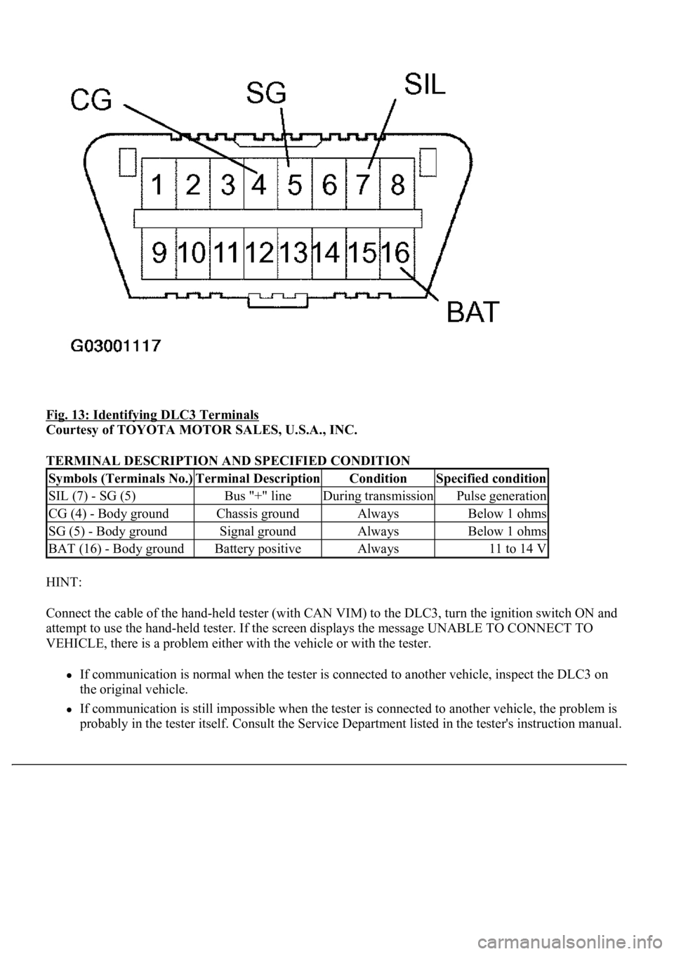
Fig. 13: Identifying DLC3 Terminals
Courtesy of TOYOTA MOTOR SALES, U.S.A., INC.
TERMINAL DESCRIPTION AND SPECIFIED CONDITION
HINT:
Connect the cable of the hand-held tester (with CAN VIM) to the DLC3, turn the ignition switch ON and
attempt to use the hand-held tester. If the screen displays the message UNABLE TO CONNECT TO
VEHICLE, there is a problem either with the vehicle or with the tester.
If communication is normal when the tester is connected to another vehicle, inspect the DLC3 on
the original vehicle.
If communication is still impossible when the tester is connected to another vehicle, the problem is
probably in the tester itself. Consult the Service Department listed in the tester's instruction manual.
Symbols (Terminals No.)Terminal DescriptionConditionSpecified condition
SIL (7) - SG (5)Bus "+" lineDuring transmissionPulse generation
CG (4) - Body groundChassis groundAlwaysBelow 1 ohms
SG (5) - Body groundSignal groundAlwaysBelow 1 ohms
BAT (16) - Body groundBattery positiveAlways11 to 14 V