Page 1774 of 4500
signal data.
Fig. 35: Display E And
- -
Courtesy of TOYOTA MOTOR SALES, U.S.A., INC.
WATER TEMPERATURE GAUGE:
WATER TEMPERATURE GAUGE FAIL-SAFE REFERENCE
FUEL SIGNAL (FUEL INJECTION SIGNAL):
FUEL SIGNAL (FUEL INJECTION SIGNAL) FAIL-SAFE REFERENCE
FUEL SIGNAL (GAUGE SIGNAL):
ConditionResponseRecovery
Water temperature data is interrupted for
5 seconds.The gauge needle indicates
below "C".Water temperature data is
received.
ConditionResponseRecovery
While the ignition switch is in the ON
position, the fuel injection signal is
interrupted for 60 seconds.Fuel gauge calibration is
performed using average fuel
consumption data.The ignition switch is turned
from off to on and normal
data is received.
Page 1877 of 4500
Fig. 26: Inspecting Fins Blockage
Courtesy of TOYOTA MOTOR SALES, U.S.A., INC.
STANDARD SPECIFICATION
If the fins are bent, straighten them with a screwdriver or pliers.
Never apply water directly onto the electronic components.
COMPONENTS
Injection DistanceInjection Pressure
300 mm(11.81 in.)2,942 to 4,903 kPa (30 to 50 kgf cm2 , 427 to 711 psi)
500 mm (19.69 in.)4,903 to 7,845 kPa (50to80kgf cm2 , 711 to 1,138 psi)
Page 2030 of 4500
RENAULT
RENAULT - IMPORTED CARS & TRUCKS
ROLLS-ROYCE
ROLLS-ROYCE - IMPORTED CARS & TRUCKS
SAAB
SAAB - IMPORTED CARS & TRUCKS
928STop Front Of Engine
944 SeriesOn Left Side Of Engine Compartment
ApplicationConnector Location
Sportwagon
Engine DiagnosticOn Center Of Firewall
Fuel Injection DiagnosticRight Rear Of Engine Compartment,
Behind Airflow Meter
ApplicationConnector Location
All Models
1996-00In Glove Compartment
2001-Under Left Side Of Dash
ApplicationConnector Location
900 Series
1986-90In Front Of Fuse/Relay Panel
1991-93Under Back Seat, On Right Side
1994
ConvertibleUnder Rear Seat
HatchbackUnder Steering Column
All OthersUnder Right Front Seat
Page 2036 of 4500

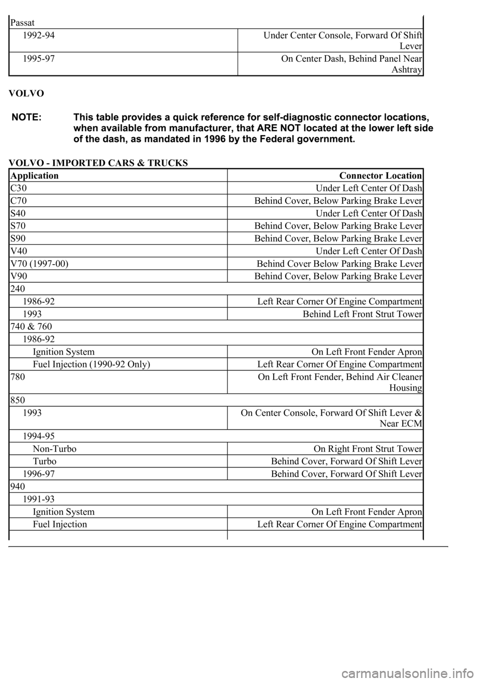
VOLVO
VOLVO - IMPORTED CARS & TRUCKS
Passat
1992-94Under Center Console, Forward Of Shift
Lever
1995-97On Center Dash, Behind Panel Near
Ashtray
ApplicationConnector Location
C30Under Left Center Of Dash
C70Behind Cover, Below Parking Brake Lever
S40Under Left Center Of Dash
S70Behind Cover, Below Parking Brake Lever
S90Behind Cover, Below Parking Brake Lever
V40Under Left Center Of Dash
V70 (1997-00)Behind Cover Below Parking Brake Lever
V90Behind Cover, Below Parking Brake Lever
240
1986-92Left Rear Corner Of Engine Compartment
1993Behind Left Front Strut Tower
740 & 760
1986-92
Ignition SystemOn Left Front Fender Apron
Fuel Injection (1990-92 Only)Left Rear Corner Of Engine Compartment
780On Left Front Fender, Behind Air Cleaner
Housing
850
1993On Center Console, Forward Of Shift Lever &
Near ECM
1994-95
Non-TurboOn Right Front Strut Tower
TurboBehind Cover, Forward Of Shift Lever
1996-97Behind Cover, Forward Of Shift Lever
940
1991-93
Ignition SystemOn Left Front Fender Apron
Fuel InjectionLeft Rear Corner Of Engine Compartment
Page 2906 of 4500
EVAP-VSV
EVAP Vacuum Switching Valve
FR
Fill Pipe Restrictor
HO2S
Heated Oxygen Sensor
MIL
Malfunction Indicator Light
ORVR-COV
On-Board Refueling Vapor Recovery Cut-Off Valve
ORVR-OCKV
On-Board Refueling Vapor Recovery Overfill Check Valve
PCV
Positive Crankcase Ventilation
SFI
Sequential Multiport Fuel Injection
SPK-CC
SPK Computer Controlled
TWC
Three-Way Catalytic Converter
WU-TWC
Warm-Up Three-Wa
y Catalytic Converter
Page 3167 of 4500

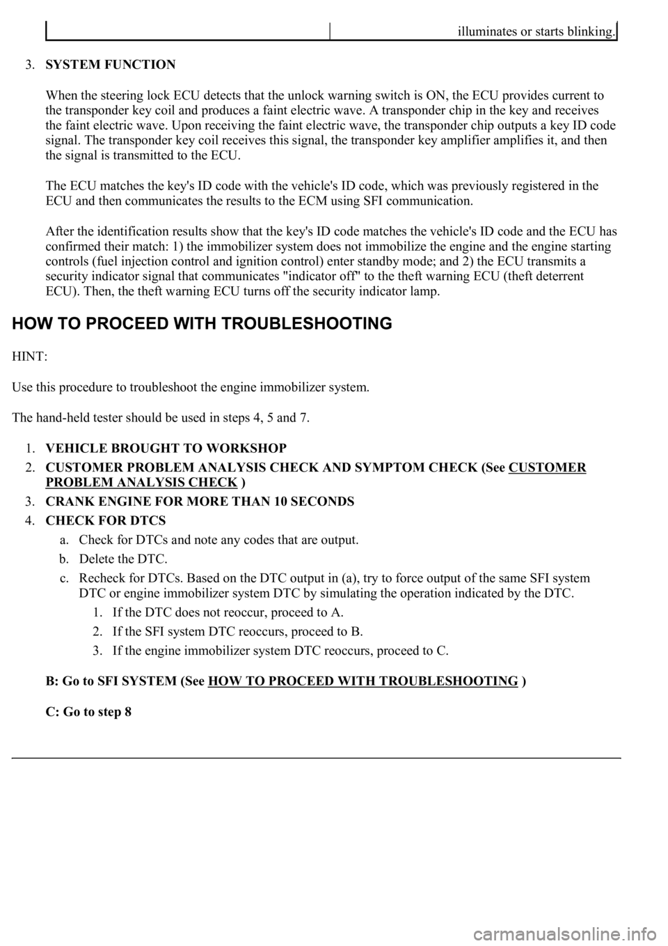
3.SYSTEM FUNCTION
When the steering lock ECU detects that the unlock warning switch is ON, the ECU provides current to
the transponder key coil and produces a faint electric wave. A transponder chip in the key and receives
the faint electric wave. Upon receiving the faint electric wave, the transponder chip outputs a key ID code
signal. The transponder key coil receives this signal, the transponder key amplifier amplifies it, and then
the signal is transmitted to the ECU.
The ECU matches the key's ID code with the vehicle's ID code, which was previously registered in the
ECU and then communicates the results to the ECM using SFI communication.
After the identification results show that the key's ID code matches the vehicle's ID code and the ECU has
confirmed their match: 1) the immobilizer system does not immobilize the engine and the engine starting
controls (fuel injection control and ignition control) enter standby mode; and 2) the ECU transmits a
security indicator signal that communicates "indicator off" to the theft warning ECU (theft deterrent
ECU). Then, the theft warning ECU turns off the security indicator lamp.
HINT:
Use this procedure to troubleshoot the engine immobilizer system.
The hand-held tester should be used in steps 4, 5 and 7.
1.VEHICLE BROUGHT TO WORKSHOP
2.CUSTOMER PROBLEM ANALYSIS CHECK AND SYMPTOM CHECK (See CUSTOMER
PROBLEM ANALYSIS CHECK )
3.CRANK ENGINE FOR MORE THAN 10 SECONDS
4.CHECK FOR DTCS
a. Check for DTCs and note any codes that are output.
b. Delete the DTC.
c. Recheck for DTCs. Based on the DTC output in (a), try to force output of the same SFI system
DTC or engine immobilizer system DTC by simulating the operation indicated by the DTC.
1. If the DTC does not reoccur, proceed to A.
2. If the SFI system DTC reoccurs, proceed to B.
3. If the engine immobilizer system DTC reoccurs, proceed to C.
B: Go to SFI SYSTEM (See HOW TO PROCEED WITH TROUBLESHOOTING
)
C: Go to step 8
illuminates or starts blinking.
Page 3227 of 4500

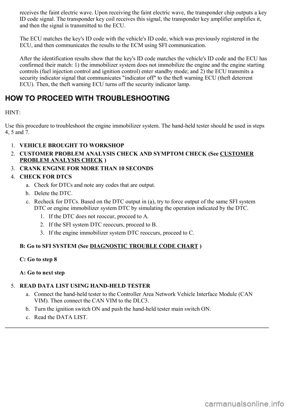
receives the faint electric wave. Upon receiving the faint electric wave, the transponder chip outputs a key
ID code signal. The transponder key coil receives this signal, the transponder key amplifier amplifies it,
and then the signal is transmitted to the ECU.
The ECU matches the key's ID code with the vehicle's ID code, which was previously registered in the
ECU, and then communicates the results to the ECM using SFI communication.
After the identification results show that the key's ID code matches the vehicle's ID code and the ECU has
confirmed their match: 1) the immobilizer system does not immobilize the engine and the engine starting
controls (fuel injection control and ignition control) enter standby mode; and 2) the ECU transmits a
security indicator signal that communicates "indicator off" to the theft warning ECU (theft deterrent
ECU). Then, the theft warning ECU turns off the security indicator lamp.
HINT:
<00380056004800030057004b004c00560003005300550052004600480047005800550048000300570052000300570055005200580045004f00480056004b00520052005700030057004b0048000300480051004a004c005100480003004c00500050005200
45004c004f004c005d0048005500030056005c005600570048[m. The hand-held tester should be used in steps
4, 5 and 7.
1.VEHICLE BROUGHT TO WORKSHOP
2.CUSTOMER PROBLEM ANALYSIS CHECK AND SYMPTOM CHECK (See CUSTOMER
PROBLEM ANALYSIS CHECK )
3.CRANK ENGINE FOR MORE THAN 10 SECONDS
4.CHECK FOR DTCS
a. Check for DTCs and note any codes that are output.
b. Delete the DTC.
c. Recheck for DTCs. Based on the DTC output in (a), try to force output of the same SFI system
DTC or engine immobilizer system DTC by simulating the operation indicated by the DTC.
1. If the DTC does not reoccur, proceed to A.
2. If the SFI system DTC reoccurs, proceed to B.
3. If the engine immobilizer system DTC reoccurs, proceed to C.
B: Go to SFI SYSTEM (See DIAGNOSTIC TROUBLE CODE CHART
)
C: Go to step 8
A: Go to next step
5.READ DATA LIST USING HAND-HELD TESTER
a. Connect the hand-held tester to the Controller Area Network Vehicle Interface Module (CAN
VIM). Then connect the CAN VIM to the DLC3.
b. Turn the ignition switch ON and push the hand-held tester main switch ON.
c. Read the DATA LIST.
Page 4118 of 4500
Using an ohmmeter, measure the resistance between the terminals.
Standard: 13.4 to 14.2 ohms at 20°C (68°F)
HINT:
If the resistance is not as specified, replace the injector.
b. Inspect the injector injection.
Fig. 19: Inspecting Injector Injection
Courtesy of TOYOTA MOTOR SALES, U.S.A., INC.
c. Disconnect the fuel pipe No. 2 from the fuel main tube.
d. Temporarily install SST (union) to the fuel pipe No. 2.
SST 09268-41047 (09268-52011)
e. Ti
ghten the flare nut on the fuel main tube (see PRECAUTION).