2003 Lancia Ypsilon Owner handbook (in English)
-
 1
1 -
 2
2 -
 3
3 -
 4
4 -
 5
5 -
 6
6 -
 7
7 -
 8
8 -
 9
9 -
 10
10 -
 11
11 -
 12
12 -
 13
13 -
 14
14 -
 15
15 -
 16
16 -
 17
17 -
 18
18 -
 19
19 -
 20
20 -
 21
21 -
 22
22 -
 23
23 -
 24
24 -
 25
25 -
 26
26 -
 27
27 -
 28
28 -
 29
29 -
 30
30 -
 31
31 -
 32
32 -
 33
33 -
 34
34 -
 35
35 -
 36
36 -
 37
37 -
 38
38 -
 39
39 -
 40
40 -
 41
41 -
 42
42 -
 43
43 -
 44
44 -
 45
45 -
 46
46 -
 47
47 -
 48
48 -
 49
49 -
 50
50 -
 51
51 -
 52
52 -
 53
53 -
 54
54 -
 55
55 -
 56
56 -
 57
57 -
 58
58 -
 59
59 -
 60
60 -
 61
61 -
 62
62 -
 63
63 -
 64
64 -
 65
65 -
 66
66 -
 67
67 -
 68
68 -
 69
69 -
 70
70 -
 71
71 -
 72
72 -
 73
73 -
 74
74 -
 75
75 -
 76
76 -
 77
77 -
 78
78 -
 79
79 -
 80
80 -
 81
81 -
 82
82 -
 83
83 -
 84
84 -
 85
85 -
 86
86 -
 87
87 -
 88
88 -
 89
89 -
 90
90 -
 91
91 -
 92
92 -
 93
93 -
 94
94 -
 95
95 -
 96
96 -
 97
97 -
 98
98 -
 99
99 -
 100
100 -
 101
101 -
 102
102 -
 103
103 -
 104
104 -
 105
105 -
 106
106 -
 107
107 -
 108
108 -
 109
109 -
 110
110 -
 111
111 -
 112
112 -
 113
113 -
 114
114 -
 115
115 -
 116
116 -
 117
117 -
 118
118 -
 119
119 -
 120
120 -
 121
121 -
 122
122 -
 123
123 -
 124
124 -
 125
125 -
 126
126 -
 127
127 -
 128
128 -
 129
129 -
 130
130 -
 131
131 -
 132
132 -
 133
133 -
 134
134 -
 135
135 -
 136
136 -
 137
137 -
 138
138 -
 139
139 -
 140
140 -
 141
141 -
 142
142 -
 143
143 -
 144
144 -
 145
145 -
 146
146 -
 147
147 -
 148
148 -
 149
149 -
 150
150 -
 151
151 -
 152
152 -
 153
153 -
 154
154 -
 155
155 -
 156
156 -
 157
157 -
 158
158 -
 159
159 -
 160
160 -
 161
161 -
 162
162 -
 163
163 -
 164
164 -
 165
165 -
 166
166 -
 167
167 -
 168
168 -
 169
169 -
 170
170 -
 171
171 -
 172
172 -
 173
173 -
 174
174 -
 175
175 -
 176
176 -
 177
177 -
 178
178 -
 179
179 -
 180
180 -
 181
181 -
 182
182 -
 183
183 -
 184
184 -
 185
185 -
 186
186 -
 187
187 -
 188
188 -
 189
189 -
 190
190
 102
fG
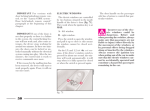
FRONT SIDE LIGHTS
To replace the 12V-5W bulb (type
W5W):
1)Remove the cover B (fig.10)by
turning partially in an anti-clockwise
direction.
2)Slide out bulb holder C (fig. 12)
by turning it slig")
 103
fG
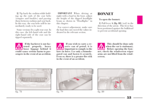
FRONT DIRECTION
INDICATORS
To replace the 12V-21W bulb (type
PY21W):
1)Release spring clip A (fig. 13)
from support Bby turning in the di-
rection of the arrow.
2)Pull out the lens unit from t")
 REAR LIGHT CLUSTER
1)From inside the car boot, lift the
carpeting and undo screw A (fig. 19)
securing the light cluster.
2)Remove the light cluster B.
3)Replace the burnt-out bulb by
pushing it slight")
 105
fG
E- 12V-21/5W (type R5W) for the
brake and taillights.
F- 12V-5W (type R5W) for the tail-
lights.
G- 12V-21W (type P21W) for the
rear foglights.
5)Refit the lighting cluster, and
tighten screw A")
 106
fG
IF AN INTERIOR
LIGHT BURNS OUTrounding it, by inserting the tip of a
screwdriver between the cover frame
and the second frame as illustrated in
(fig. 25).
CEILING LIGHT
(all other versions)
To")
 Before replacing a fuse,
make sure the key has
been taken out from the ig-
nition and that all users are
switched off or deactivated.
107
fG
BOOT LIGHT
To change the 12V-5W (type C5W)
bulb, remove the")
 108
fG
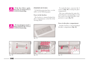
POSITION OF FUSES
To find the protection fuses, see the
tables on the following pages.
Fuses in the fusebox
The fusebox is situated behind the
glove compartment, to the left of the
steering whe")
 109
fG
Fuses in the engine compartment
A fusebox located near the positive
battery terminal contains six high am-
perage fuses which further protect the
car from the risk of fire by preventing
the hig")